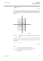
Characteristic1:
This parameter gives the type of time delay to be used. The setting
can be,
Definite time
or
Inverse curve A
or
Inverse curve B
or
Inverse curve C
. The
choice is highly dependent of the protection application.
Un>
: Set overvoltage operate value for step
n
(
n
=step 1 and 2), given as % of residual
voltage corresponding to global set parameter
UBase
:
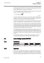
( )
( )
%
3
U
UBase kV
>
×
IECEQUATION2290 V1 EN
(Equation 71)
The setting is dependent of the required sensitivity of the protection and the system
earthing. In non-effectively earthed systems the residual voltage can be maximum the
rated phase-to-earth voltage, which should correspond to 100%.
In effectively earthed systems this value is dependent of the ratio Z0/Z1. The required
setting to detect high resistive earth-faults must be based on network calculations.
tn
: time delay of step
n
(
n
=step 1 and 2), given in s. The setting is highly dependent of
the protection application. In many applications, the protection function has the task
to prevent damages to the protected object. The speed might be important for example
in case of protection of transformer that might be overexcited. The time delay must be
co-ordinated with other automated actions in the system.
t1Min
: Minimum operate time for inverse time characteristic for step 1, given in s. For
very high voltages the overvoltage function, using inverse time characteristic, can
give very short operation time. This might lead to unselective trip. By setting
t1Min
longer than the operation time for other protections such unselective tripping can be
avoided.
k1
: Time multiplier for inverse time characteristic. This parameter is used for co-
ordination between different inverse time delayed undervoltage protections.
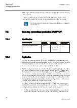
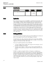
7.4
Loss of voltage check LOVPTUV
7.4.1
Identification
Function description
IEC 61850
identification
IEC 60617
identification
ANSI/IEEE C37.2
device number
Loss of voltage check
LOVPTUV
-
27
7.4.2
Application
The trip of the circuit breaker at a prolonged loss of voltage at all the three phases is
normally used in automatic restoration systems to facilitate the system restoration
after a major blackout. Loss of voltage check (LOVPTUV) generates a TRIP signal
only if the voltage in all the three phases is low for more than the set time. If the trip
1MRK 505 291-UEN A
Section 7
Voltage protection
165
Application manual
Summary of Contents for Relion REQ650
Page 1: ...Relion 650 series Breaker protection REQ650 Application manual ...
Page 2: ......
Page 20: ...14 ...
Page 26: ...20 ...
Page 48: ...42 ...
Page 82: ...76 ...
Page 90: ...84 ...
Page 160: ...154 ...
Page 178: ...172 ...
Page 264: ...258 ...
Page 288: ...282 ...
Page 302: ...296 ...
Page 330: ...324 ...
Page 338: ...332 ...
Page 339: ...333 ...

