9.10
IO Setup
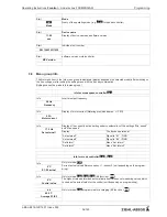
Main menu
IO Setup
Protocol
Base setup
Controller Setup
IO Setup
Limits
9.10.1
Analog-Output
“
A
”
IO Setup
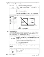
The analog outputs 0 - 10 V can be allocated with various functions.
Terminals
“
A
”
-
“
GND
”
= AnalogOut (I
max
Technical data)
Constant voltage 10 V
(1A)
A Function
IO Setup
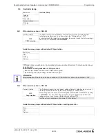
With the attitudes
“
A min
”
and
“
A max
”
the characteristic of the output voltage can be
adapted.
Setting range:
“
A min.
”
= 0 - 5 V,
“
A max.
”
= 10 - 5 V
Factory setting:
“
A min.
”
= 0 V,
“
A max.
”
= 10 V
0.0 V
A min.
IO Setup
10.0 V
A max.
IO Setup
With the attitudes
“
A Inverting
”
the output voltage can inverted.
Factory setting:
“
A Inverting
”
=
“
OFF
”
OFF
A Inverting
Function
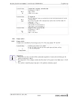
Description
OFF
No function
Constant voltage 10 V
(1A)
Constant v10 V (factory setting)
1st control signal
(2A)
Proportional to the internal activation of the power unit (control circuit 1) under consid-
eration of
“
Min. Speedl
”
and
“
Max. Speed
”
.
•
for enable
“
OFF
”
it goes back to 0 V
•
for motor fault the output signal remains for a slave controller (
“
Master-Slave
”
combination).
E1
(3A)
proportional input
“
E1
”
E2
(4A)
proportional input
“
E2
”
Group2
(5A)
Group control (
Controller Setup - group 2)
2.Cooling
(6A)
Only in mode
2.03
temperature controller with additional functions (not for Z-Module-
B).
Controller output 2 with rising activation at Actual>Nominal =
Cool
.
2.Heating
(7A)
Only in mode
2.03
temperature controller with additional functions (not for Z-Module-
B).
Controller output 2 with rising activation at Actual<Nominal =
Heat
.
Operating Instructions
Fcontrol
–
model series FXDM25/32AM
Programming
L-BAL-E212-GB 1451 Index 003
Part.-No.
66/123


