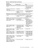
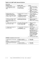
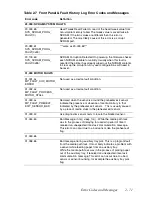

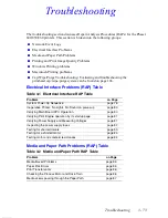


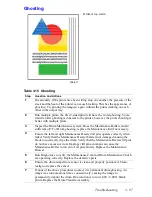
Troubleshooting
3 - 83
Testing for shorted drivers
1.
Turn off the printer.
2.
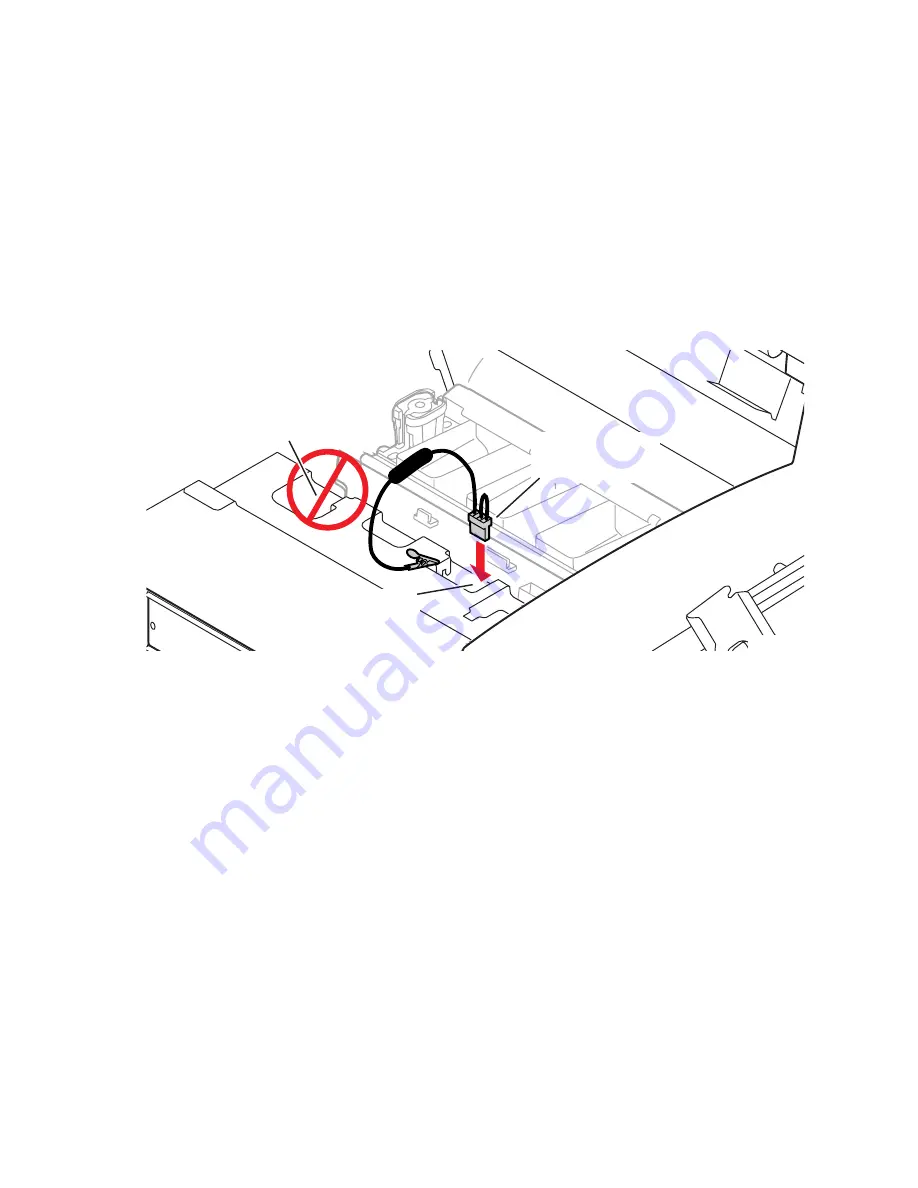
Disconnect the +40 DC loopback connector (the 4-pin connector with the two
loopback wires) from J250 at the top of the power control board. (This isolates the
Y-axis motor, process motor, X-axis motor, paper feed motor, vacuum pump, solenoids
and clutches).
3.
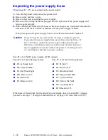
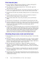
The 40 volt service load connector is not needed for the Phaser 860 printer, go to step
4. For the Phaser 840/850 attach the service load connector to J250 on the top of the
power control board (behind the printhead) to simulate a load on the power supply.
Attach the service load connector’s ground clip to the printer frame. Do not leave the
service load connector in place and powered-up for longer than 5 minutes; it gets hot
from the current load.
4.
Turn on the printer. If the rear panel LEDs illuminate (indicating power), the power
control board or its loads are current-limiting the power supply. Go to Step 5. If no
power is evident (no lighted LEDs), replace the power supply.
5.
Turn off the printer. Reconnect the +40 volt loopback connector to the power control
board; then disconnect all load connectors from the power control board. Turn on the
printer. If the rear panel LEDs still do not illuminate, the power control board has a
shorted driver and must be replaced. If the LEDs do illuminate, isolate which motor or
fan is overloading the power control board and power supply. Turn off the printer.
Sequentially plug each cable in one at a time, and turn on the printer until the power
supply is disabled. Replace the defective component. Also refer to the next topic,
"Testing motor and solenoid resistances" on page 3-84.
6.
Turn off the printer. Disconnect the two I/O board ribbon cables from the power
control board. (This isolates the I/O boards and their solenoid drivers.) If the
rear-panel LEDs illuminate, isolate which I/O board is shorting or which I/O board
ribbon cable is defective.
7.
If the power supply still does not work, replace the power supply.
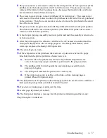
Fig 3-1 Attaching the service load connector to J250
0388-66
Service load
connector
J 250
Warning: AC voltage
hazard. Never attempt
to plug service load
connector here.
Содержание Phaser 840
Страница 2: ......
Страница 12: ...vi Phaser 840 850 860 8200 Color Printer Service Manual ...
Страница 52: ...1 36 Phaser 840 850 860 8200 Color Printer Service Manual ...
Страница 88: ...2 72 Phaser 840 850 860 8200 Color Printer Service Manual Blank Page ...
Страница 134: ...3 118 Phaser 840 850 860 8200 Color Printer Service Manual ...
Страница 174: ...4 158 Phaser 840 850 860 8200 Color Printer Service Manual ...
Страница 188: ......
Страница 250: ...8 234 Phaser 840 850 860 8200 Color Printer Service Manual ...
Страница 286: ...270 Phaser 840 850 860 8200 Color Printer Service Manual ...
Страница 287: ...071 0723 00 ...