3 - 78
Phaser 840/850/860/8200 Color Printer - Service Manual
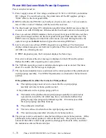
Phaser 860 Customer Mode Power-Up Sequence
Power switch is turned on:
1.
Power supply senses AC line voltage conditions (110 VAC or 220 VAC) and enables
DC voltages. If an overload occurs, the printer turns off the DC supplies, giving a
“blink” effect to the front panel LEDs.
2.
BIST test flashes the PE LED very breifly at a fast rate (for only 1/3 of a second at a
rate of 8 Hz; a total of 3 flashes) until the end of the next test.
3.
The Boot loader performs CPU initialization and RAM test (RAM test is less than 0.1
seconds, even with 256 Mbytes). It then sends the boot loader version to the serial port.
4.
Power-on self-test (POST) initializes the front panel; front panel LED turns red, then
green, then orange and then off, the front panel LCD goes black and then clear. The
POST version is displayed on the LCD and waits two seconds. During this time the
operator can press the
Back
button to bypass the remaining POST test.
5.
Low level power-on self-test (POST) diagnostics are performed. The front panel
displays status messages as each sub-test is performed. This test takes about 8 seconds.
All LEDs are off during the test.
If POST diagnostics pass, the front panel displays the Xerox logo.
If an error is detected, the error message is displayed on the LCD and the printer
flashes the LEDs with a repeating error code pattern.
6.
The VxWorks operating system is initialized and engine code is started. This takes
about 15 seconds. The Xerox logo is displayed.
7.
The mechanical initialization is conditional on the initial position of the printhead and
cap/wipe/purge assembly. Two NVRAM parameters are checked for the last known
position.
If the printhead is in either the Locked or Print position:
a.
The cap/wipe/purge motor is run to ensure that the cap/wipe/purge
assembly activates its home-position sensor.
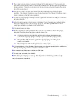
If the printhead is in the cap/wipe/purge position:
a.
The heaters in the printhead and cap/wipe/purge assembly are activated, as
a precaution, to melt the ink which may have cooled and solidified, thus
gluing the cap/wipe/purge and printhead together. 10 minutes pass while
the cap/wipe/purge assembly heats up.
b.
The printhead is tilted back.
c.
The ink is allowed to drain from the cap/wipe/purge assembly.
d.
The cap/wipe/purge assembly is lowered to its home position.
8.
The process motor is activated to rotate the head tilt gear into its home position. (If the
printhead is in the locked position it will not tilt forward.) The process motor also
rotates all the rollers to their ready positions, disengage the transfix roller, and lower
the maintenance drawer blade and wiper.
Содержание Phaser 840
Страница 2: ......
Страница 12: ...vi Phaser 840 850 860 8200 Color Printer Service Manual ...
Страница 52: ...1 36 Phaser 840 850 860 8200 Color Printer Service Manual ...
Страница 88: ...2 72 Phaser 840 850 860 8200 Color Printer Service Manual Blank Page ...
Страница 134: ...3 118 Phaser 840 850 860 8200 Color Printer Service Manual ...
Страница 174: ...4 158 Phaser 840 850 860 8200 Color Printer Service Manual ...
Страница 188: ......
Страница 250: ...8 234 Phaser 840 850 860 8200 Color Printer Service Manual ...
Страница 286: ...270 Phaser 840 850 860 8200 Color Printer Service Manual ...
Страница 287: ...071 0723 00 ...

