background image


Page 69 


touch control from the Main Screen

f)


Additional 3G/HD/SD-SDI cards added to the AMP2-16V will have their 
own separately adjustable delay. 

g)


The adjustable delay for the internal monitor speakers, as set in the 

Monitor Mixer Configuration Menu

, if used, will be in addition to the 

SDI Audio Delay


5.1 Downmix Parameters Screen 

This menu allows you to set the audio attenuation levels that will be applied to the 
channels by pressing the Downmix hot key. These parameters apply to the 

downmix that appears externally through the Analog or AES outputs, as well as to 
the internal speaker mix. The selected mix will be LoRo, unless a Downmix hot key 

enables LtRt and is activated. 


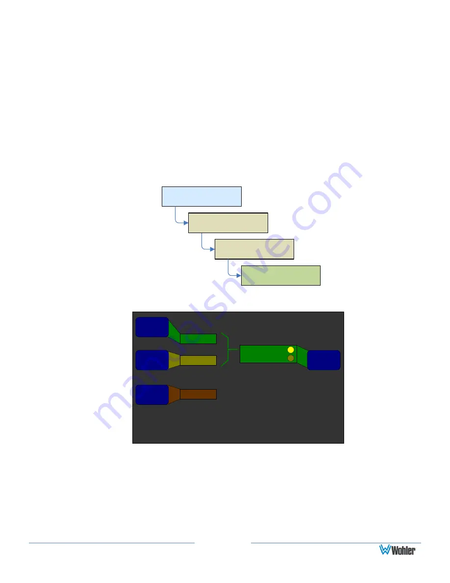
5.1 Downmix Parameters

Configuration Selection 

Menu

Main Screen

Configure 

Options

Option 

Configuration Menu

5.1 Downmix 

Parameters


Figure 5–4:  5.1 Downmix Parameters Screen 

5.1 Downmix Parameters

Help

Save / Exit

Cancel

Surround 

Mix Level

Center Mix 

Level

Overall 

Offset 

Level

-3 dB

-3 dB

0 dB

Parameter 

Source

Fixed Settings

Metadata Values

Adjust settings according 

to the Metadata Source 

selection in the Metadata 

Select Menu. 


1.


Center Mix Level: Rotating this knob selects between four possible level 

reductions for the center channel in the downmix: 0 dB-3 dB-4.5 dB, or -

6 dB


2.


Surround Mix Level: Rotating this knob selects between three possible 
level reductions for the surround channels in the downmix:  -3 dB-6 dB, or 

Mute

Содержание AMP2-16V-M

Страница 1: ...AMP2 16V Series AMP2 16V M AMP2 E16V M Modular Audio Video Management and Monitoring Platform User Guide Software Release V7 xx Part Number 821116 Revision M...

Страница 2: ...eviewed the documentation Wohler Technologies Inc makes no warranty or representation either express or implied with respect to software documentation their quality performance merchantability or fitn...

Страница 3: ...etup in a Preset 13 Getting Support 14 CHAPTER 2 Installation 15 Introduction 15 Overview 15 Important Safety Instructions 15 Installation Recommendations 16 Mounting 16 Heat Dissipation 16 Sympatheti...

Страница 4: ...he Main Screen 43 How do I Show Mixer Output Levels on the Level Meters 44 How Do I Configure the Audio Inputs or Outputs 45 How Do I Set the Clock Source 46 How Do I Terminate Unterminate AESInputs 4...

Страница 5: ...3 Loudness Measurement Menu 94 Main Screen Configuration Menu 96 Metadata Select Menu 97 Meter Configuration Menu 99 Monitor Mixer Configuration Menu 101 Option Configuration Menu 104 Preset Managemen...

Страница 6: ...Precautions 128 Requirements 128 Adding a Dolby D E DD Card 129 Removing a Dolby D E DD Card 135 Adding an I O Module 135 Adding a 3G Option Card 135 Adding a Non 3G Card I O Module 136 Removing an I...

Страница 7: ...avenna Network Setup 155 Introduction 155 Ravenna Input Module Features 155 RAVENNA Compatible Listener 155 AVB Ethernet Features 156 BACH Controller Interface 156 Home Page 157 Configuration Device M...

Страница 8: ...s release What s New There is now support for the 16 channel Dante Receiver card Appendix A describes how to set it up within an existing Dante AoIP network There is also support for the 16 channel Ra...

Страница 9: ...p knob controls the Volume Pressing this control sequences through a 20 dB speaker dip mute and then back to the current volume The bottom knob adjusts the Balance between the speakers Pressing the kn...

Страница 10: ...creen Configuration Menu In our example in Figure 1 2 below the Video Data button will switch the left screen display from video to data Figure 1 2 Main Screen 28 1 LKFS Swap Video Data Meta 0 Dolby Z...

Страница 11: ...p You can display help for any individual knob or button For example press the Help button on any screen and then press one of the menu screen controls to display help specific to that control See Fig...

Страница 12: ...igure 1 5 provides a number of feature adjustments only a few are needed for you to get started The other feature adjustments are explained later in this manual in Chapter 5 Menu List Figure 1 5 Monit...

Страница 13: ...ll source each of the displayed and monitored pairs rotate the Mixer Channel Select knob to the channel pair and then use the Source Pair Select to pick a channel pair from the available inputs 4 Then...

Страница 14: ...Cluster Label to display the Label Menu Figure 1 7 Figure 1 7 Label Menu Label Menu Save Exit Help Cancel Backspace Select Vert Select Existing Label Shift Select Horiz Revert a b c d e f g h i j k l...

Страница 15: ...see how the various screen arrangements will appear Figure 1 8 Main Screen Configuration Menu Main Screen Configuration Menu Help Configure Meters Configure Loudness Screen Content Left Screen Right S...

Страница 16: ...2020 Line Number 14 Dolby Line Position Pair 3 N P Dolby Line Position Pair 4 N P Note The Lines of data on this display are arranged exactly as they will appear on the Main Screen 2 Rotate the Line S...

Страница 17: ...ple Rate RF Compression Profile Center Surround Mix Lev Stereo Downmix LtRt Cntr Srnd Downmix Level LFE Lowpass Filter Original Bitstream Dialogue Level Press to Configure Metadata Source 2 Rotate the...

Страница 18: ...ate RF Compression Profile Center Surround Mix Lev Stereo Downmix LtRt Cntr Srnd Downmix Level LFE Lowpass Filter Original Bitstream Dialogue Level Press to Configure Metadata Source 8 Rotate the Line...

Страница 19: ...E Channel Disabled Surround Mode Not Srnd Encoded Mdata Scroll CRC Error Reporting On 3 Rotate the Decoder Source knob to select the source for the Dolby D E DD Card The choices include all available...

Страница 20: ...Level LFE Lowpass Filter Original Bitstream Dialogue Level Press to Configure Metadata Source Note Any text line can contain any metadata element 15 Rotate the Line Selectknob to scroll the highlight...

Страница 21: ...tate the Save Current Config control to the number of the preset you would like to save the configuration into and then press the knob 4 You will be presented with the opportunity to name the preset T...

Страница 22: ...he power cord from being walked on or pinched particularly at plug s source on the equipment and at the socket 6 Use only the attachments accessories specified by the manufacturer 7 Unplug the equipme...

Страница 23: ...tic Vibration Sympathetic vibration from other equipment cables etc in the rack may be serious enough to interfere with the unit s sound quality The use of thin card stock and or felt or foam weather...

Страница 24: ...10 150W 50 60Hz power supply module A second identical module is an optional accessory for use when redundancy is necessary These modules plug in to the back panel and are secured with thumbscrews Th...

Страница 25: ...factory diagnostic purposes 4 Genlock Ref Input and Pass Through Ref These BNC connectors are designed to be used in a daisy chained series arrangement from unit to unit A 75 BNC terminator not suppli...

Страница 26: ...Rx channels of Dante 8 Rx channels of AES67 Ravenna AEC67 AoIP Card 16 Rx channels of Ravenna 8 Rx channels of AES67 Dolby Card D E DD Card Provides Dolby bitstream decoding for an AES pair or de embe...

Страница 27: ...rview This chapter answers many questions that naturally come up as the AMP2 16V Series monitor is first put into service Notation In this chapter we use a shorthand method to show you how to progress...

Страница 28: ...nfigure Options Video SDI Source Monitor Mixer Configuration Menu Save Exit Help Cancel Chan 1 Chan 2 Chan 3 Chan 4 Slot 2 SDI 3G In Pair 4 Slot 1 AES In Pair 1 0 0 0 0 Channel Trim Source Pair Select...

Страница 29: ...Chan 3 Chan 4 Slot 2 SDI 3G In Pair 4 Slot 2 SDI 3G In Pair 5 0 0 0 0 Channel Trim Source Pair Select Phase LED On Off Delay to Speakers 170 mS Audio Delay Dolby 5 1 Speaker Mute Off L Front R Front C...

Страница 30: ...50 P a i r 1 P a i r 2 P a i r 3 P a i r 4 P a i r 5 P a i r 6 P a i r 7 P a i r 8 Cluster Configuration Screen Save Exit Help Cancel 1 2 Cluster Start Edit Cluster Label Cluster End Select Cluster D...

Страница 31: ...0 Pair 5 5 Select Cluster Channels 15 16 Pair 8 8 Pair 8 Pair 7 Pair 6 Pair 5 Clust 1 Clust 2 Clust 3 Select Cluster Channels 7 8 Pair 4 4 Clust 4 1 Using the hot key that is in the location you want...

Страница 32: ...ontinuous Manual Mode Off Over Alarm Both Under Momentary Short Term Custom 3 Sec Loudness Window 1 Use the Loudness Standard knob to set the standard you need 2 Use the Mode knob to set whether you w...

Страница 33: ...0 0 0 0 L Front R Front Center LFE Yes Yes Select Affect Main Volume Affect Mixer Channel Select Output Trim Output 1 Output 2 Output 3 Output 4 7 1 Outputs Height Output Group Select 1 Press the Fol...

Страница 34: ...o present clusters with more than 8 channels you must have two analog output cards installed in the system Use the Output Group Select control to determine which analog output card carries the first 8...

Страница 35: ...it Help Cancel Off 1 2 3 4 5 6 7 8 Selectable Dolby Zoom 1 3 5 7 9 11 13 15 2 4 6 8 10 12 14 16 AES Out 4 Trim AES Mic Channe 29 Recall Preset Press for Stat Meta Status Metadata Off Dolby Zoom Key 7...

Страница 36: ...r Mixer Configuration Menu Monitor Mixer Configuration Menu Save Exit Help Cancel Chan 1 Chan 2 Chan 3 Chan 4 Slot 2 SDI 3G In Pair 4 Slot 2 SDI 3G In Pair 5 0 0 0 0 Channel Trim Source Pair Select Ph...

Страница 37: ...associated audio on your surround sound system Then proceed to the 3G SDI Input Configuration Menu Configuration Selection Menu Main Screen Menu Audio Processors Audio Processor Card Menu 3G SDI I O...

Страница 38: ...nels can be monitored at the same time if desired ClusterSelect hot keys associated with those bitstreams will automatically change into Dolby Zoom hot keys Then you will be able to press these Dolby...

Страница 39: ...d from Den 24 Status Metadata Preset Data Pre Key 2 LtRt LoRo Auto Mode Automation On Off 1 Turn the control associated with the hot key you want Dolby Zoomto be on so that the long bar not the contro...

Страница 40: ...oder Configuration Menu Dolby Decoder Configuration Menu Save Exit Help Cancel Decoder Source Pro 16 Mode Channel Dolby E Program Slot 1 AES In Pair 1 Channel 1 Program 1 Decode Aux Pair DRC Mode All...

Страница 41: ...e Pair Select Phase LED On Off Delay to Speakers 170 mS Audio Delay Dolby 5 1 Speaker Mute Off L Front R Front Center LFE Channel Func Mixer Channel Select Set Clusters 1 Use the Mixer Channel Select...

Страница 42: ...60 0 60 50 40 30 10 20 10 20 30 40 50 60 0 D o l b y 5 1 D o w n M i x A E S 1 A E S 2 A n l g 1 A n l g 2 Anlg 2 The flag is red for a few seconds when a count is added and then it turns yellow 1 To...

Страница 43: ...play the line position of each Dolby E bitstream contained in a 3G HD SD SDI signal for guard band checking This may be shown for any or all Dolby E bitstreams simultaneously on the same screen As wit...

Страница 44: ...ain Data Screen the you can press the Status Metadata control to display the Status Screen which contains the Dolby line position data Figure 3 16 Data Screen Status Select Menu Help Save Exit Cancel...

Страница 45: ...sometimes need to monitor you could set up system configurations for each scenario up to a total of 32 configurations Since a preset is a complete system configuration first set up all of the paramete...

Страница 46: ...6 Configuration Menu Configure Hot Keys Figure 3 18 Hot Key Configuration Menu Hot Key 9 16 Configuration Menu Save Exit Help Cancel Off 1 2 3 4 5 6 7 8 Selectable Dolby Zoom 1 3 5 7 9 11 13 15 2 4 6...

Страница 47: ...gure 3 19 Monitor Mixer Configuration Menu Monitor Mixer Configuration Menu Save Exit Help Cancel Chan 1 Chan 2 Chan 3 Chan 4 Slot 2 SDI 3G In Pair 4 Slot 2 SDI 3G In Pair 5 0 0 0 0 Channel Trim Sourc...

Страница 48: ...ute the SuperPair audio This setup is done in the Hardware Configuration Menu Configuration Selection Menu Main Screen Menu Configure Options Option Configuration Menu Hardware Configuration Menu Conf...

Страница 49: ...15 2 4 6 8 10 12 14 16 1 3 5 7 9 11 13 15 2 4 6 8 10 12 14 16 1 3 5 7 9 11 13 15 2 4 6 8 10 12 14 16 Pan 0 0 0 0 Mix Input Select Chan 1 Chan 2 Chan 3 Chan 4 Mixer Channel Select Channel Trim Follow M...

Страница 50: ...1 3 5 7 9 11 13 15 2 4 6 8 10 12 14 16 AES Out 4 Trim AES Mic Channe 29 Recall Preset Press for Stat Meta Status Metadata Off Dolby Zoom Key 7 Trim Key 1 Rec 1 Key 5 Stat Mdata Downmix Dnmix Key 8 SDI...

Страница 51: ...the monitor mixer to be metered The internal pathways used for this feature are also used by the TOSLINK Card Output free mix channel pairs will appear as sources in the Monitor Mixer Configuration Me...

Страница 52: ...to configure an input or output card in one of the slots go to the Audio Processor Card Menu Configuration Selection Menu Main Screen Menu Audio Processors Audio Processor Card Menu Figure 3 24 Audio...

Страница 53: ...elected Slot 4 AES In Pair 1 8 hours Screen Saver Screen Bright Balance Control Menu Lock SuperPair Balance Left Right 16 32 1 Turn the Clock Source knob to select the preferred clock and press it Thi...

Страница 54: ...p is done in the AES Input Configuration Menu Configuration Selection Menu Main Screen Menu Audio Processors Audio Processor Card Menu AES Input Card Configuration AES Input Configuration Menu Figure...

Страница 55: ...Menu Lock combination by pressing the encoders to indicate the desired combination To unlock the first menu hold the center navigation button and press the combination Current Status Lock Enabled 1 I...

Страница 56: ...ption Configuration Menu Hardware Configuration Menu Configure Hardware Unit Information Menu Unit Info Figure 3 28 Unit Information Screen Unit Information Menu Exit Application AMP2 16 V Application...

Страница 57: ...ring As a channel cluster is selected for listening its arrow indicators brighten Refer to How Do I Select the Inputs I Want to Hear in the Speakers in this chapter The header at the top of the screen...

Страница 58: ...dicators The loudness for the selected cluster is also calculated and displayed both numerically and graphically depending on the settings in the Loudness Clusters Menu When the chosen Select Cluster...

Страница 59: ...nd Downmix Level LFE Lowpass Filter Original Bitstream Dialogue Level SMPTE 2020 Metadata Page 1 Trim 0 dB Dolby 5 1 Pair 2 SDI 1 M trak AES ANLG Status Meta Pair 3 SOLO 0 28 1 LKFS Menu Swap Help 3 S...

Страница 60: ...by Digital Sample Rate RF Compression Profile Center Surround Mix Lev Stereo Downmix LtRt Cntr Srnd Downmix Level LFE Lowpass Filter Original Bitstream Dialogue Level SMPTE 2020 Metadata Page 1 28 1 L...

Страница 61: ...certain audio program Loudness is measured and displayed automatically for that program on the Main Screen Loudness Screen For more in depth Loudness measurements as well as either Continuous or Start...

Страница 62: ...ttom of the central column 7 The name of the currently monitored cluster is shown in the footer at the bottom of the screen 8 2 8 Level Meters for the channels being monitored for loudness are shown o...

Страница 63: ...nput sources Refer to the 1 Configure the Monitor Mixer section in Chapter 1 for details Note that you can set up multiple audio paths For example while monitoring de embedded SDI audio channels throu...

Страница 64: ...coder Src 2 Pro 16 Mode Decode 5 Aux Pair 6 3 Dolby E Pgm DRC Mode 7 Up to 5 X 4 Analog Output MixPairs 4 CRC Error Mdata Scroll 8 Up to 4 X 8 AES Output Mix Pairs AESOutputs 1 Pair from Monitor Mix M...

Страница 65: ...hannel pairs These outputs can be derived from other inputs decoded Dolby channels or the flexible internal audio mixer according to preset and menu settings 4 AVB Listener Card This card provides a 1...

Страница 66: ...put these delayed signals as needed through the de embedded AES output ports or the optional AES and analog output ports The effect of the delay can be audibly monitored continuously as it is changed...

Страница 67: ...I Want to Hear in the Speakers in Chapter 3 for details Wide Selection of Video Formats Video formats are automatically selected The following formats are supported Table 4 1 Supported Video Formats...

Страница 68: ...ay be nothing to worry about but multiple errors are an indication of a signal problem and this display will allow you to make that judgment Dolby Zoom Screen Dolby Zoom is a very powerful analysis to...

Страница 69: ...n Menu 3 You selected Auto for the Decodetype in the Dolby Configuration Menu To display the Dolby Zoom screen from the Main Screen press a Dolby Zoom hot key For detailed instructions for creating a...

Страница 70: ...ter or audio from a satellite receiver or cable box Refer to How Do I Set Up a SuperPair to Monitor Intercom or Other Sources in Chapter 3 for details Standard and Custom Meter Scales The AMP2 16V Ser...

Страница 71: ...resets allows you to tailor the AMP2 16V to the ever increasing number variety and challenging monitoring needs of the broadcast industry providing one touch control of even major system changes and r...

Страница 72: ...ective options and functions Note The menus are listed alphabetically for easy reference Menu Navigation Overview The Menu Tree shown in Figure 5 1 describes how to navigate from one screen to another...

Страница 73: ...er 2 Analog Ref 3 4 Unit Info 5 Factory Def 6 Bal Super Pr 7 Menu Lock 8 AES Output Configuration Menu Free Mix 1 Mixer Ch Sel 2 Channel Trim 3 4 5 Mix Input Sel 6 Pan 7 Output Assgn 8 Analog Output C...

Страница 74: ...Output Assign Pan 0 0 0 0 Mix Input Select Chan 1 Chan 2 Chan 3 Chan 4 Mixer Channel Select Channel Trim SDI Audio Delay 80 mS 1 3 5 7 9 11 13 15 2 4 6 8 10 12 14 16 1 3 5 7 9 11 13 15 2 4 6 8 10 12 1...

Страница 75: ...are installed this menu is accessible This menu allows the customer to select the SDI Audio Delay a The SDI Audio Delay will be applied to all 16 de embedded channels of the 3G HD SD SDI input and the...

Страница 76: ...lected mix will be LoRo unless a Downmix hot key enables LtRt and is activated 5 1 Downmix Parameters Configuration Selection Menu Main Screen Configure Options Option Configuration Menu 5 1 Downmix P...

Страница 77: ...ttings are used Rotating this control selects either Fixed Settings or Metadata Values AES Input Configuration Menu This menu allows you to set the termination on the input connectors Configuration Se...

Страница 78: ...uts or AES Output Configuration Menu Configuration Selection Menu Main Screen Audio Processors Audio Processor Card Menu Analog or AES Output Card Configuration Analog Output Configuration Menu The me...

Страница 79: ...ge of 60 dB to 12 dB inclusive in 1 dB increments You can mute the channel by turning the knob counterclockwise beyond 60 dB Pressing and holding this knob returns the setting to 0 dB 3 Select Affect...

Страница 80: ...en the mixer strips Other controls then affect the mixer strip 1 Channel Trim Rotating this knob changes the gain on the selected channel This control has a range of 60 dB to 12 dB inclusive in 1 dB i...

Страница 81: ...es monitor Arbitrary Phase Measurement Menu Configuration Selection Menu Main Screen Menu Configure Main Screen Main Screen Configuration Menu Configure Arbitrary Phase Figure 5 8 Arbitrary Phase Meas...

Страница 82: ...hip Note The colors for each arbitrary phase indication are automatically and sequentially selected Note The same channel may not be both a Reference Channel and a Test Channel Note Any given Referenc...

Страница 83: ...t signals in this menu 2 Analog Input Output Pressing a knob with this description displays the Analog Output Configuration Menu In this menu signals can be mixed to output through the analog outputs...

Страница 84: ...by D E DD Card if installed and display live Dolby metadata In this screen the source of the Dolby metadata can be set along with other parameters If the AMP2 16V is not equipped with the Dolby D E DD...

Страница 85: ...curs You can therefore override any automated change at any time And your changes stay in effect until the current condition is removed and then met again or until another condition is met As long as...

Страница 86: ...tating this control displays one of 32 presets that can be recalled when the Select Condition is met Adding an Auto Mode Hot Key By setting up an Auto Mode hot key you can quickly and easily turn the...

Страница 87: ...on Menu they will appear gray on the Cluster Configuration Screen Moreover they will not appear at all on the Main Screen and the remaining meters will automatically redistribute themselves to display...

Страница 88: ...form two clusters of eight channels each four clusters of four channels each or eight clusters of two channels each Configuration Selection Menu The Configuration Selection Menu allows you to modify m...

Страница 89: ...s control appears when one or more 3G SDI cards are installed Rotating this knob moves the red selection box from input to input on each installed card Pressing this knob selects the input source from...

Страница 90: ...Onor Off 4 Metadata can be reviewed For convenience you can access the Dolby Decoder Configuration menu as one of the Audio Processor cards Configuration Selection Menu Main Screen Menu Audio Processo...

Страница 91: ...ignored 3 Dolby E Program A Dolby E bitstream can contain up to eight separate audio programs with metadata This control selects the program to monitor both audio and metadata It also selects the pro...

Страница 92: ...If the same type of Dolby bitstream is always expected then select that type However if any of the other formats can be expected to appear at various times and must be decoded then select All Formats...

Страница 93: ...oders and other A V equipment b Dialnorm Only This selection sets the Dolby decoder to operate in exactly the same way as in the None setting except that on Dolby E bitstreams the Dialnorm is adjusted...

Страница 94: ...255 255 Unit Name Wohler s AMP2 16V 255 255 255 255 IP Mask 255 255 255 255 Gateway 255 255 255 255 DNS 255 255 255 255 Adjust 1 Unit Name Pressing this knob displays the Label Menu where you can ass...

Страница 95: ...rt of a preset The Clock Source is saved as part of each preset Configuration Selection Menu Main Screen Menu Configure Options Option Configuration Menu Hardware Configuration Menu Configure Hardware...

Страница 96: ...evels a 22 dBFS 4 dBu b 20 dBFS 4 dBu c 18 dBFS 4 dBu d 16 dBFS 4 dBu e 20 dBFS 8 dBu f 20 dBFS 0 dBu g 18 dBFS 0 dBu h 9 dBFS 6 dBu 3 Screen Bright Press this knob to toggle the screen whose brightne...

Страница 97: ...nu Configure Hot Keys Figure 5 18 Main Screen Hot Key Configuration Menu Hot Key 1 8 Configuration Menu Save Exit Help Cancel Select Cluster Channels 3 4 Pair 2 2 Select Cluster Channels 1 2 Pair 1 1...

Страница 98: ...s highlighted selects it and allows further detailing of the function of some of the hot keys Note Multiple trim hot keys cannot adjust the same channels on the same menu so channels that are not sele...

Страница 99: ...t Pressing this knob toggles between upper and lower case letters Rotating it left selects upper case rotating it right selects lower case The letters inside the dark area of the screen change accordi...

Страница 100: ...osen to be measured Loudness Measurement Menu Configuration Selection Menu Main Screen Menu Configure Main Screen Main Screen Configuration Menu Configure Loudness Loudness Clusters Menu Loudness Clus...

Страница 101: ...ness Standard EBU R128 9 Scale Loudness Measurement Menu Reference Level LRA Window 23 0 LKFS 9 Seconds 3 Sec Momentary Short Integrate Loudness Window Integration Period Continuous Manual Mode Off Ov...

Страница 102: ...The alarm will then be activated if the measured loudness exceeds the Alarm Tolerance For example if Over or Both is selected and the Reference Level is exceeded by the Alarm Tolerance the Loudness S...

Страница 103: ...use loudness to be monitored all of the time Main Screen Configuration Menu This menu provides links to other menus where you can configure the meters clusters other options hot keys and loudness sett...

Страница 104: ...the highlighted option The yellow indicator identifies the current option 5 Configure Arbitrary Phase Pressing this knob displays the Arbitrary Phase MeasurementMenu See Arbitrary Phase Measurement M...

Страница 105: ...Decoder Configuration Menu respectively 2 Line Select Rotating this knob scrolls the highlight up or down among the lines of text to select the line you want to modify 3 Metadata Page Rotating this k...

Страница 106: ...Configuration Menu Configure Meters Figure 5 24 Meter Configuration Menu Meter Configuration Menu Save Exit Help Cancel AES IEC1 VU 0 dBr 72 dBr 12 30 dBr 15 20 dBr 0 dBr 0 dBFS 4 Float Bar Top Botto...

Страница 107: ...to reach 2 dB of settled reading 20 dB 1 7 sec IEC Type II 10 ms to reach 2 dB of settled reading 24 dB 2 8 sec None Bar or Floating Segment Not Displayed 3 Limits Rotating this knob sets the upper li...

Страница 108: ...nd top limits of the meter 8 Middle Segment Color Rotating this knob cycles the middle color of the displayed sample level meter color through a wide variety of colors Pressing this knob allows adjust...

Страница 109: ...nitor mixer channel and pair to configure 3 Channel Func Rotating this knob selects either LFront R Front Center LE L Sur R Sur L Rear Sur R Rear Sur M Sur or None 1 Channel Trim Rotating this knob ch...

Страница 110: ...ining meters will automatically scale and rearrange themselves to fill the void 5 Speaker Mute On Off Rotating or pressing this knob turns the knob label on or off When the Speaker Mute is On no sound...

Страница 111: ...ther you can select a single cluster or multiple clusters to be heard at once 2 Monitor Mixer Trims Rotating or pressing this control determines whether the eight pairs of Channel Trim controls on the...

Страница 112: ...Preset Management Menu Save Exit Help Cancel Preset 4 User Preset 4 Preset 1 User Preset 1 Preset 1 User Preset 1 Current Config Current Settings Preset 1 User Preset 1 Preset 4 User Preset 4 Clear Pr...

Страница 113: ...lugged and then subsequently powered up the unit can either start up in its last known state or in the selected preset Note None of the preset modifications are saved until the Save Exit button is pre...

Страница 114: ...5 29 Select Menu Lock Combination Screen Disabled Select Menu Lock Combination Save Exit Help Cancel Key 5 Key 6 Key 3 Key 1 Key 2 Key 4 Key 7 Key 8 Select Menu Lock combination by pressing the encod...

Страница 115: ...Main Screen See 4 Select the Metadata to Display on the Screen in Chapter 1 for more information Configuration Selection Menu Main Screen Menu Configure Main Screen Main Screen Configuration Menu Meta...

Страница 116: ...ting metadata list Status Select Menu This menu allows you to select the content and display font size and color of the status information you want to display on the screens Configuration Selection Me...

Страница 117: ...creen This can be used to separate the data lines so they are easier to read The height of the blank line is controlled by the Font Size control Unit Information Menu This menu allows you to display t...

Страница 118: ...emotely when updating software via the Ethernet 2 Unit S W Info Pressing this knob displays the version of each software component in the unit and the I O modules that this unit contains 3 Ethernet Se...

Страница 119: ...as other available options for the AMP2 16V Series monitors Distinctions Among Models Optional I O Modules You can further customize the AMP2 16V by inserting additional I O modules a total of five t...

Страница 120: ...by D E DD Card is a daughter card and does not occupy one of the vacant slots since it does not require its own external connectors Standard Models While a huge number of functional combinations are p...

Страница 121: ...selected BNC will appear on the Monitor Mixer Configuration Menu Menu Modifications Outputs The eight AES output pairs on this card are de embedded and re clocked from the 3G HD SD SDI signal No other...

Страница 122: ...below Note The unbalanced AES output pin out is the same as a commercially available VGA to BNC cable Table 6 3 Unbalanced AES Output Connector Pin Out Pin AES Outputs 1 thru 4 Function AES Outputs 5...

Страница 123: ...ctors shown in Figure 6 3 Figure 6 3 AES Input Card Rear Panel Adaptor and Rear Card Cover Plate Menu Modifications All of the AES input pairs on the AES Input Card rear panel adaptor are selectable o...

Страница 124: ...he rear panel adaptor provides the connectors shown in Figure 6 6 Figure 6 4 AES Output Card Rear Panel Adaptor and Rear Card Cover Plate Menu Modifications Pressing the AES Out knob from the Audio Pr...

Страница 125: ...as shown in Figure 6 5 Figure 6 5 AVB Listener Card Rear Panel Adaptor Menu Modifications All of the AVB input pairs become selectable in the Monitor Mixer Configuration Menu and are also sources on...

Страница 126: ...analog input from the Monitor Mixer Configuration Menu and also from the AES and Analog Output Menus The Audio Processor Configuration Menu will now display an Analog I O knob Pressing this knob will...

Страница 127: ...Input 10 Channel 2 Non inverted Balanced Analog Input 11 Ground Channel 2 Shield 12 Channel 1 Inverted Balanced Analog Input 13 NC Not Used 14 Channel 8 Inverted Balanced Analog Input 15 Channel 7 No...

Страница 128: ...d 9 Channel 3 Inverted Balanced Analog Output 10 Channel 2 Non inverted Balanced Analog Output 11 Ground Channel 2 Shield 12 Channel 1 Inverted Balanced Analog Output 13 NC Not Used 14 Channel 8 Inver...

Страница 129: ...Output Menus The Audio Processor Configuration Menu will now display an Analog I O knob Pressing this knob will display the Analog Output Configuration Menu from which you can select and configure th...

Страница 130: ...r Panel Adaptor After adding the Dante Receiver card and its corresponding rear panel cover to the AMP2 16V Series monitor the Dante AoIP Ethernet connector will appear as shown in Figure 6 8 Figure 6...

Страница 131: ...hown in Figure 6 9 Figure 6 9 Ravenna Receiver Card Rear Panel Adaptor Menu Modifications 16 of the Ravenna Receiver channels become selectable in the Monitor Mixer Configuration Menu and are also sou...

Страница 132: ...r Supply To install an additional power supply position the monitor with the rear panel facing you and follow the instructions below 1 Remove the power cord 2 Using a small Phillips screwdriver remove...

Страница 133: ...the blank cover plate and remove the cover plate 3 Slide the power supply into the slot from the rear panel making sure that the power supply s connector seats securely into the connector inside the...

Страница 134: ...ting connector for this option Table 6 6 DC Power Specifications Specification Value Voltage Input Range 20VDC to 30VDC Input Current Typical 2A Max 5A Note The AMP2 16V monitor will not operate if th...

Страница 135: ...ductor devices Avoid handling the circuit boards in high static environments such as carpeted areas and when synthetic or wool fiber clothing is worn Touch the frame to dissipate static charge before...

Страница 136: ...power cord s 2 Using a small Phillips screwdriver remove the top cover Figure 6 12 Remove Bottom Screw 3 Pull the monitor so that it slightly hangs over the edge of the surface on which it is sitting...

Страница 137: ...rear panel adaptor for the system control board as shown in Figure 6 14 above 6 Gently unplug the ribbon cable from the system board Figure 6 15 Remove System Control Board 7 Gently tilt the system b...

Страница 138: ...ounded Figure 6 16 above illustrates the card and the two standoffs left and the four screws right Figure 6 17 Attach First Standoff Standoff Screw from the Other Side 9 Attach a standoff to the side...

Страница 139: ...ond Standoff Standoff Screw from the Other Side 10 Attach the second standoff similarly as shown in Figure 6 18 above Figure 6 19 Insert Dolby D E DD Card 11 Insert the Dolby D E DD Card into the slot...

Страница 140: ...system control board and then attach another screw on top of the standoff as shown in Figure 6 20 above Figure 6 21 Tighten Second Standoff Screw 13 Similarly adjust and tighten the second standoff sc...

Страница 141: ...ecurely connected as shown in Figure 6 22 Generally this board does not snap in 15 Connect the ribbon cable to the system card Figure 6 23 Replace Rear Panel 16 Replace the rear panel as shown in Figu...

Страница 142: ...nel for the new I O module s slot Remember to save the four screws for the new rear panel cover plate 4 Remove the 3G Option Card from its shipping container being careful to remain grounded 5 When yo...

Страница 143: ...I O module in the empty slot until the I O module snaps in securely 6 Attach the rear panel connectors to the card and screw it to the rear panel frame 7 Replace the lid and the screws WARNING Do not...

Страница 144: ...rear panel opening with a blank rear panel cover 6 Insert the rear panel cover screws and tighten 7 Replace the lid and the screws Note All presets will be set to a factory default appropriate for the...

Страница 145: ...Cover Plate 919313 3G SDI I O Module 750645 2 Cables 15 Pin VGA Female to IDC 16 Pos Female 6 LG 829001 AES Input Option Kit includes 256455 01 919256 and 919282 256455 01 AES Input Rear Cover Plate...

Страница 146: ...stem control board P N 919323 so it does not have a rear panel adaptor or a rear panel cover plate includes 919210 281422 x4 and 285050 x2 919210 Dolby D E DD Decoder Module 281422 4 Screws 4 40 x 3 1...

Страница 147: ...l including advertisements discovery and enumeration The AVB Ethernet interface is capable of communicating at up to 100 Mbits s The Dante and Ravenna Ethernet interfaces are capable of communicating...

Страница 148: ...peak per channel Frequency Response 60 Hz 16 kHz 5 dB 10 dB 50 Hz 20 kHz AES EBU Input Termination 75 Ohms unbalanced switchable SDI Input Termination 75 Ohms unbalanced AES EBU Sampling Rate 48kHz An...

Страница 149: ...the normal operation of the unit No IP Address If you are attempting to connect your AMP2 16V Series monitor to your network and you see this message displayed on the Unit Information Menu refer to E...

Страница 150: ...d Detected PS1 8AES Input Board 8 AES Input Board PS2 3G SDI Input Board 3G SDI Input Board PS3 3G SDI I O Board 3G SDI I O Board PS4 8 AES Output Board 8 AES Output Board PS5 8 In 8 Out analog Board...

Страница 151: ...gain Call Wohler Technical Support if this problem persists Minor Issue In the event of the following error please print the report and have it available before contacting Wohler s customer support Fi...

Страница 152: ...t the report and have it available before contacting Wohler s customer support Figure 8 6 Serial Port Access Message Serial Port Access The system has encountered an operation error Cycle the power on...

Страница 153: ...Chan 3 Chan 4 Slot 2 Dante Pair 4 Slot 2 Dante Pair 5 0 0 0 0 Channel Trim Source Pair Select Phase LED On Off Delay to Speakers 170 mS Audio Delay Dolby 5 1 Speaker Mute Off L Front R Front Center LF...

Страница 154: ...ovides an interface to 1 Manage connections with ease a Display discovered devices and streams b Connect streams from network to local destinations c Start stop and monitor stream health status 2 Enab...

Страница 155: ...ponsible for most device configurations and all audio routing The setup screen for Channel and Audio Routing is shown in Figure A 2 Figure A 2 Channels and Audio Routing Assignments iAM Dante AoIP RX...

Страница 156: ...is is not recommended Dante practice and as such is not a normally tested configuration Figure A 3 IP Address Configuration Leave at the Default Setting Up to sixteen AoIP receive channels can be moni...

Страница 157: ...pear that way on the network Figure A 4 Dante Device Name Dante Device Name Figure A 5 Device Name Change Change the AoIP Name Other changes such as Latency settings can be made by the Dante Controlle...

Страница 158: ...upted It functions as an accurate slave clock synchronized to the master clock on the network when not operating as the master Figure A 6 Preferred Master Clock Selection Preferred Master Clock Channe...

Страница 159: ...ec packet times can be received 24 bit linear L24 encoding and 1 msec packet time are fixed default transmit parameters Device View AES67 Config menu enables disables AES67 Figure A 7 AES67 Enable Dis...

Страница 160: ...he Dante Controller File menu Create Multicast Flows window Figure A 9 Multicast Channel Selection Device Lock There a feature whereby a remote controller can send a command to lock Dante network devi...

Страница 161: ...acbook is used use MT Merging Technology discovery program to check network traffic to locate the card Wireshark is a free and open sourced packet analyzer software program It can be used to analyze n...

Страница 162: ...lay Dolby 5 1 Speaker Mute Off L Front R Front Center LFE Channel Func Mixer Channel Select Set Clusters Note In addition to the AMP2 16V configuration the Coveloz Bach board needs to configured using...

Страница 163: ...ream e 512 512 Channels of audio f 48kHz and 96kHz sampling rates 2 IEEE 802 1Q SRP 3 IEEE 1722 1 AVDECC control 4 IEEE 802 1AS gPTP 5 Compatible with Apple OS X devices such as MacBooks and MacMini c...

Страница 164: ...by writing down the new IP address and affixing it to the rear panel cover plate of the associated Ravenna option card for your future reference Figure B 2 BACH Controller Home Page Configuration Dev...

Страница 165: ...in Figure B 3 Note ALL Devices must use the same packet time or sources or destinations may not be available If you change any setting on the Device Configuration page click Save Running to Startup If...

Страница 166: ...alled After the configuration described in the previous section the devices you have set up should now appear on the Controller Cloud page Note All devices must be on the same subnet to be discovered...

Страница 167: ...interval announce interval etc The default values should be sufficient Likewise although there are a number of clocking options packet times and announcement times available the default values should...

Страница 168: ...na signals from devices on the network Check the Source tab of the source card web page At lease one source much be turned on Figure B 6 shows a Source page with six sources turned on The status of ea...

Страница 169: ...TDM 1 Figure B 7 BACH Controller Stream Destinations In the event that the Patch tab will not allow you to route to TDM 0 or TDM 1 use this tab to delete all sources routed to those destinations by cl...

Страница 170: ...Page 163 Figure B 8 Deleting Stream Destinations...

Страница 171: ...g the listeners bottom The AMP2 16V is a destination only Although many may be shown in the list you may route only to the TDM 0 and TDM 1 columns from any available source as follows TDM 0 Ravenna Pa...

Страница 172: ...ll help determine whether the IP address was changed or simply entered incorrectly 2 Use software such as Wireshark to check network traffic 3 Empty the cache of the browser Cannot route to a destinat...

Отзывы: