background image

180

250050 R1

Model 3008CEW-ED2 to 3012CEW-ED2
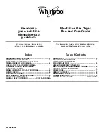
Figure 140.

Model 3008CEW-ED2 and 3009CEW-ED2

A

194681 [RED]

8 REQ’D

STANDARD

194783 2 REQ’D

BOTTOM SHORT

194681 [RED]

9 REQ’D

BOTTOM

194780 [RED]

2 REQ’D

3008CEW-ED2

194607 [BLACK]

10 REQ’D

194681 [RED]

6 REQ’D

194681 [RED]

8 REQ’D

194681 [RED]

10 REQ’D

194681 [RED]

8 REQ’D

C

E

E

194681 [RED]

10 REQ’D

*SEE NOTE 1

C

C

E

STANDARD

S

194681 [RED]

8 REQ’D

194607 [BLACK]

10 REQ’D

194681 [RED]

6 REQ’D

194681 [RED]

8 REQ’D

194681 [RED]

8 REQ’D

194681 [RED]

10 REQ’D

194681 [RED]

10 REQ’D

194681 [RED]

9 REQ’D

BOTTOM

194783 2 REQ’D

BOTTOM SHORT

3009CEW-ED2

194780 [RED]

2 REQ’D

194681 [RED]

10 REQ’D

E

*SEE NOTE 1

Notes:

1.

See

Figure 146 on page 186

for detailed layout view.

2.

Colors

match part number label and indicate wall sheet thickness.

3.

Stencil sheets are 194656 and 194659 [YELLOW].

4.

Walk-in door 236810 (supplied with 2 door boards).

5

All uprights except for the top “S” and 232772 catwalk upright are 2 tiers long.

9. SPECIFICATIONS

EASYDRY® WIDE-CORR CENTURION® GRAIN BIN – GRAIN BIN DRYER

Содержание EasyDry Wide-Corr Centurion 24 Series

Страница 1: ...injury death or property damage Keep manual for future reference Part Number 250050 R1 Revised July 2019 EasyDry Wide Corr Centurion Grain Bin Grain Bin Dryer Installation and Operator s Instructions This manual applies to the following grain bin models 2407 2410 2707 2712 3008 3012 3608 3612 Original Instructions ...

Страница 2: ...equired for this product This product has been designed and constructed according to general engineering standards other local regulations may apply and must be followed by the operator Use the sign off sheet below to record initial and periodic reviews of this manual with all such personnel Date Employee Signature Employer Signature ...

Страница 3: ...Tagout Safety 16 2 14 1 Electric Motor Safety 17 2 14 2 Hydraulic Power Safety 18 2 15 Auxiliary Equipment Safety 18 2 16 Personal Protective Equipment 19 2 17 Safety Equipment 20 2 18 Safety Decals 20 2 19 Decal Installation Replacement 20 2 20 Safety Decal Locations and Details 20 3 Features 24 3 1 Exterior Bin Views 24 3 2 Plenum End View 25 4 Before You Begin 26 4 1 Bin Design and Capacity 26 ...

Страница 4: ...all Plenum Stiffeners to Sidewall 52 6 13 Install Connection Plates and Tension Segments 53 6 14 Support the Plenum Peak Ring 54 6 15 Assemble Rafter Pre Assemblies 55 6 16 Install Quarter Point Rafter Pre Assemblies 57 6 17 Finish Rafter Pre Assemblies Installation 60 6 18 Install Rafter Braces or Purlins 61 6 19 Install Peak Plates 63 6 20 Install the Peak Ring Cross Member 63 6 21 Prepare to In...

Страница 5: ...lat Roof Cap Assembly 128 6 41 Inspection Hatch Details 129 6 42 Inspection Hatch Reinforcing Plate 130 6 43 Wall Sheet and Bottom Angle Assembly 131 6 44 Commercial Bin Upright Assembly 132 6 44 1 Base Assembly 138 6 45 Wind Ring Assembly 140 6 46 Walk In Door and Sampling Hatch Installation 142 6 46 1 Sampling Hatch 24 and 27 Installation 143 6 46 2 Sampling Hatch 30 and 36 Installation 144 6 46...

Страница 6: ...187 10 1 1 Plenum Parts 187 10 1 2 Plenum Hardware 192 10 1 3 Dump Hoppers and Dump Chute Necks 193 10 1 4 Winch Hand Operated 193 10 1 5 CEW ED Common Parts Box Listing 7 9 Tier Bins 194 10 1 6 CEW ED Non Common Pail Parts Box Listing 7 9 Tier Bins 196 10 1 7 CEW ED Common Parts Box Listing 10 12 Tier Bins 197 10 1 8 CEW ED Non Common Pail Parts Box Listing 10 12 Tier Bins 198 10 1 9 CEW ED2 Comm...

Страница 7: ...ltural use as listed below Use in any other way is considered as contrary to the intended use Compliance with and strict adherence to the conditions of operation and maintenance as specified by the manufacturer also constitute essential elements of the intended use The grain dryer should be operated maintained serviced and repaired only by persons who are familiar with its particular characteristi...

Страница 8: ...nd related SAFETY information contained in this manual Remember YOU are the key to safety Good safety practices not only protect you but also the people around you Make these practices a working part of your safety program All accidents can be avoided It is the grain dryer owner operator and maintenance personnel s responsibility to read and understand ALL safety instructions safety decals and man...

Страница 9: ...nd liquids in the vicinity of dryer Do not use the dryer where a high concentration of grain dust or flammable liquids or vapors exist such as milled grain dust Use the dryer only with the gas types intended connecting alternate fuel sources to the dryer can result in fires Shut off and lock out or disconnect power and close valve at gas source before inspecting or servicing the heater or when not...

Страница 10: ...ty Have another trained person nearby who can shut down the grain dryer in case of accident The work area should be kept clear of bystanders Keep the work area clean and free of debris 2 6 Guards Safety Keep guards in place Do not operate with guard removed Do not walk on step on or damage guards Lock out power before removing a guard Ensure all guards are replaced after performing maintenance 2 7...

Страница 11: ...appropriate respirator Never walk on grain to make it flow If you ignore the safety precautions above and enter the bin you could die from being submerged 2 8 1 Roof Entry The information in this section applies to entry through the bin roof only Never enter a bin from the roof if you don t know its unloading history Bridges of stored material can form above a void space below causing potential fo...

Страница 12: ...is intended for fertilizer storage Grain flows in a funnel shaped path when unloading This vortex of grain behaves very much like a water drain Velocity increases as grain flows from the bin wall at the top of the grain mass into a small vertical column at the center of the bin Flowing grain will not support the weight of a person Submersion happens within seconds Figure 1 Suffocation Hazards in F...

Страница 13: ...the grain after having removed some of the grain If surface is undisturbed the grain has bridged and formed a crust Never walk on the grain crust The crust rarely becomes strong enough to support the weight of a person To remove bridge try breaking the bridge from the inspection hatch or peak Use a pole to hit the surface securing it with a rope in case it is dropped Be aware that chunks of cruste...

Страница 14: ...tical walls of grain are created when the bin is partially empty Poking at the wall can make the grain avalanche and submerge a person Do not enter the bin to break down grain that has set up Break grain mass from top of the bin outside Figure 3 Suffocation Hazards from a Vertical Grain Wall 2 SAFETY EASYDRY WIDE CORR CENTURION GRAIN BIN GRAIN BIN DRYER ...

Страница 15: ...ion proof lights Do not use anything around or inside the equipment that may produce a flame such as a match a lighter or anything that may produce a shower of sparks such as a grinder or power saw unless the air is free of dust and all dust deposits have been removed from the work area or the work area is wet such that dust cannot be dispersed in the air and smoldering processes from sparks canno...

Страница 16: ...and follow lockout and tagout procedures to prevent inadvertent start up and hazardous energy release Know the procedure s that applies to your equipment from the following power sources For example De energize block and dissipate all sources of hazardous energy Lock out and tag out all forms of hazardous energy Ensure that only 1 key exists for each assigned lock and that you are the only one tha...

Страница 17: ...te main power disconnect switch within reach from ground level to permit ready access in case of an emergency Motor must be properly grounded Guards must be in place and secure Ensure electrical wiring and cords remain in good condition replace if necessary Use a totally enclosed electric motor if operating in extremely dusty conditions Lockout The main power disconnect switch should be in the loc...

Страница 18: ...ngs or hoses with tape clamps or adhesive The hydraulic system operates under extremely high pressure such repairs will fail suddenly and create a hazardous and unsafe condition Lockout Always place all hydraulic controls in neutral and relieve system pressure before disconnecting or working on hydraulic system 2 15 Auxiliary Equipment Safety Unapproved auxiliary equipment could cause performance ...

Страница 19: ... hearing damage Respirator Wear a respirator with particulate cartridges to prevent breathing potentially harmful dust Coveralls Wear coveralls to protect skin Hard Hat Wear a hard hat to help protect your head Steel Toe Boots Wear steel toe boots to protect feet from falling debris Work Gloves Wear work gloves to protect your hands from sharp and rough edges Fall Arrester Use a fall arrester when...

Страница 20: ...be clean and dry with a temperature above 50 F 10 C 2 Decide on the exact position before you remove the backing paper 3 Align the decal over the specified area and carefully press the small portion with the exposed sticky backing in place 4 Slowly peel back the remaining paper and carefully smooth the remaining portion of the decal in place 5 Small air pockets can be pierced with a pin and smooth...

Страница 21: ...250050 R1 21 Figure 4 Safety Decals EASYDRY WIDE CORR CENTURION GRAIN BIN GRAIN BIN DRYER 2 SAFETY ...

Страница 22: ...hut off and lock out all power 2 Use a lifeline safety harness and have an observer outside before entering the bin 3 Wear proper breathing equipment or a respirator 4 Avoid the center of the bin Failure to heed these warnings could result in serious injury or death ENTRAPMENT HAZARD Part Number 8110 00013 WARNING Keep clear of all augers DO NOT ENTER this bin If you must enter the bin 1 Shut off ...

Страница 23: ...and or bin damage Use a minimum 1 square foot 0 1m2 opening for each 1000ft3 min 30m3 min of air Ensure all roof vents are open and unobstructed Discontinue use of aeration fan if roof vents become obstructed with ice NOTICE Part Number 8110 00066 FALL RESTRAINT ANCHOR POINT MAX WORKING LOAD 1 000 lb 453 kg SEE MANUFACTURER ROOF MANUAL FOR DETAILED INSTRUCTIONS REGARDING ANCHOR POINT LOCATIONS Par...

Страница 24: ... Exterior Bin View VENT FAN ENTRANCE SAMPLING HATCH P L C BOX programmable logic control H P U hydraulic pump unit WALK IN DOOR BIN UNLOAD EXIT ROOF PEAK CENTER FILL Important Components roof and sidewall configurations layouts and options will vary 3 FEATURES EASYDRY WIDE CORR CENTURION GRAIN BIN GRAIN BIN DRYER ...

Страница 25: ...ENER 008430 PLENUM CONE 27 006182 24 30 36 004822 DISPERSAL RING 24 30 36 004966 27 006181 LOWER DUMP HOPPER 004959 PERFORATED GRAIN BAND BRACKET 004560 PEAK PLATE 24 006196 27 006180 30 006155 36 004856 TENSION SEGMENT 24 006197 27 30 006150 36 004811 30 EasyDry Batch Plenum shown in this example DUMP HOPPER CHUTE 015034 EASYDRY WIDE CORR CENTURION GRAIN BIN GRAIN BIN DRYER 3 FEATURES ...

Страница 26: ...oads follow Upgrades are available Table 1 Peak Loads for Various Roofs Size Type of Roof Load lbs Load kg 24 non structural 4000 lbs 1814 kg 27 to 36 non structural 5000 lbs 2268 kg b Roof Snow Loads RSL at the above stated standard peak loads standard RSLs vary with diameter and range from 20 psf 97 kg m2 to 24 psf 117 kg m2 Upgrades are available Note The correlation between ground snow load GS...

Страница 27: ...ts a straight line interpolation can be used to determine maximum roof snow load 4 Higher level upgrade kits include all components from lower level kit only one upgrade kit needs to be ordered for any given bin 4 1 2 Roof Snow Load vs Ground Snow Load The Roof Design Capacity tables reflect roof snow load RSL values These are design values Often comparisons are made to ground snow values GSL Thes...

Страница 28: ...upport stiffener in Westeel bins are designed to provide vertical load support only Any lateral loads subjected to the grain bin must be negligible 4 There is a restriction of 2 upgraded catwalk support stiffeners per bin location Therefore the maximum supported load at the grain bin eave is 20 000 lbs for two 10 000 lb upgrades and 40 000 lbs for two 20 000 lb upgrades This can be repeated on the...

Страница 29: ...e for specifically stated soil conditions Bin assembly Westeel recommends the use of qualified bin installers contact Westeel for information on installers in your area Field modifications or equipment additions that affect the bin structure Interconnections with neighboring structures Compliance with all applicable safety standards including but not limited to fall restraint systems ladders or ot...

Страница 30: ...rough a bin wall 4 Opening height for fan transition shall be limited to 12 5 inches from bottom edge of a bottom wall sheet 5 Opening width shall not exceed 46 5 for stiffened bins and 72 5 for unstiffened bins 6 Vertical support shall be required to support load above opening 7 Bottom angles may be cut flush to the sides of an opening to form part of opening Openings for Unloading Augers of Wide...

Страница 31: ...ur with the initial filling 7 When installing roof stiffening rings if it is necessary to shorten the stiffening ring tubes shorten them as little as possible Initially the nuts on the expanders should be centered and as close together as possible When tightening share the amount of take up between expanders such that the nuts remain centered and the amount of engagement between all expanders on t...

Страница 32: ...ome more aggressive and turn into red rust Red rust can cause degradation in the material and become a structural concern Any parts that have red rust should be replaced immediately torage Guidelines Keep all bundles dry before assembly of the bin Start assembly as soon as possible Do not lay bundles on the bare ground raise all bundles 6 8 off the ground on wood blocks or timbers Store curved wal...

Страница 33: ...y of an 8 auger Ensure that the inner door panels of grain bin doors are completely closed and latched before filling the grain bin Never enter a loaded grain bin for any reason Grain can be a killer 4 10 Important Notes Westeel does not provide a foundation design for this product and is not liable for any damages or injuries related to inadequately designed or constructed foundations Customers m...

Страница 34: ...iple 9 16 and 1 2 sockets recommended Large pocket carpenter pouch 8 20 cm metal punches for aligning bolt holes Step and extension ladders construction grade 6 point wrenches Imperial box end Metal cutting saw suitable for cutting roof rings and wind rings Scaffolding Centre post bin stand Crane and or bin jacks Minimum Recommended Safety Equipment A properly stocked first aid kit Eye foot head a...

Страница 35: ...ontact with power lines can cause electrocution Do not work in high winds 6 2 Pre Plan Assembly Before starting assembly 1 Read and understand this manual 2 Develop an assembly plan with consideration given to the layout of accessories and auxiliary equipment 3 Predetermine the locations for access doors anchor bolts ladders manways side draws roof steps roof vents fans and other auxiliary equipme...

Страница 36: ...E WALK IN DOOR UNLOAD TUBE P L C BOX programmable logic control H P U hydraulic pump unit OPTIONAL OUTSIDE LADDER WITH LADDER CAGE INSPECTION HATCH ROOF LADDER FAN HOOD DUCTWORK FAN HEATER UNIT DISPLAY BOX not shown in this illustration ROOF SHEET PEAK OPENING WITH ROOF CAP flat roof cap shown SAMPLING HATCH 6 ASSEMBLY EASYDRY WIDE CORR CENTURION GRAIN BIN GRAIN BIN DRYER ...

Страница 37: ...250050 R1 37 6 2 2 Conductor Clearances 24 to 36 Bins EASYDRY WIDE CORR CENTURION GRAIN BIN GRAIN BIN DRYER 6 ASSEMBLY ...

Страница 38: ...t be shimmed under an upright See Section 6 44 Commercial Bin Upright Assembly on page 132 5 Locate anchor bolts as shown in Figure 9 using the dimensions provided in the following Curb Specifications tables to ensure bin roundness 6 Re bar end laps are not included Add 15 380mm for each lap To estimate weight of end lap add 0 5 lbs for 3 and 1 0 lbs for 4 0 3 kg for 10M and 0 6 kg for 15M 7 Concr...

Страница 39: ...29 3 58 3 58 3 94 3 R Metric mm c c 914 457 457 914 457 457 279 Imperial in c c 36 18 18 36 18 18 11 S Metric1 3 10M 3 10M 5 10M 3 10M 3 10M 5 10M 6 10M Imperial 5 3 4 3 4 4 4 3 4 3 4 4 5 4 T Metric1 4 10M 2 10M 4 10M 3 10M 3 10M 4 10M 6 10M Imperial 4 3 3 3 3 4 4 3 4 3 4 4 5 4 Reinforcing Rod M kgs 53 111 190 131 146 217 295 I lbs 109 232 398 270 293 508 677 Wire Mesh sq ft 422 398 380 538 505 48...

Страница 40: ...M Imperial 4 3 4 4 5 4 4 3 4 4 6 4 T Metric1 3 10M 5 10M 6 10M 3 10M 5 10M 6 10M Imperial 4 3 4 4 5 4 4 3 4 4 4 4 Reinforcing Rod M kgs 164 265 357 196 321 449 I lbs 329 571 770 384 700 1036 Wire Mesh sq ft 631 602 573 926 882 839 Concrete 3000 psi Cubic Yards Footing 10 6 18 9 23 6 12 7 24 0 31 0 Slab 7 8 11 2 10 7 11 5 16 4 15 6 1For Canadian Metric to European Standard EN 10080 BS 4449 conversi...

Страница 41: ...e 3 After the first ring of wall sheets has been assembled check the position and roundness of the ring a Verify that the maximum amount that the bin is out of round is no more than 0 75 on the radius when measured from the center of the bin b Verify that the wall sheets form a smooth circle with no flat spots or cauliflower shaped curves c Before anchoring the bin to the foundation re check to en...

Страница 42: ...9 0 117 0 194606 194737 194777 139 130 10 Black 209 4 194607 194738 194778 EasyDry Plenum Wall Sheets 057 052 17 Red 83 0 116 5 194681 194050 076 070 14 Lime 112 2 194656 194052 Stencil 194659 194053 Stencil 194683 194051 139 130 10 Black 209 4 117 0 194607 194060 Short Sheets Installed Around Fan Entrance s and Sampling Hatch 057 052 17 Red 42 59 0 194054 22 4 31 5 194056 62 6 87 8 194057 5 8 8 1...

Страница 43: ...TO SEAL GAP CAUSED BY OVERLAP OF WALL SHEETS LOCATE CAULKING AS SHOWN 4 6 4 6 5 32 x 7 32 ROLL CAULKING P N 193814 APPLY AS SHOWN USING A CONTINUOUS STRIP WALL SHEET CAULKING DETAIL Inside view shown 33 16 ft 4 20 in 60 29 ft 9 35 in 108 53 ft 7 83 in 36 17 ft 10 11 in 66 32 ft 9 16 in SEE WHERE USED CHART EASYDRY WIDE CORR CENTURION GRAIN BIN GRAIN BIN DRYER 6 ASSEMBLY ...

Страница 44: ...F CAULKING ARE USED TO SEAL GAP CAUSED BY OVERLAP OF WALL SHEETS LOCATE CAULKING AS SHOWN ASSEMBLY DIRECTION 4 mm x 6 mm ROLL CAULKING P N 193814 APPLY AS SHOWN USING A CONTINUOUS STRIP SEE WHERE USED CHART 100 mm 100 mm 150 mm 150 mm 6 ASSEMBLY EASYDRY WIDE CORR CENTURION GRAIN BIN GRAIN BIN DRYER ...

Страница 45: ... above the walk in door as shown stagger the wall sheets normally as shown below Figure 12 Stencil and Short Sheet Placement Even Tiered Bins Page C19 SHORT SHEETS SHORT SHEETS BOTTOM SHORT SHEETS 6 HOLES UPRIGHT LOCATIONS SHORT SHEETS SHORT SHEETS BOTTOM SHORT SHEETS Even Tiered Bins To align the stencil sheets above the walk in door as shown stagger the wall sheets normally as shown below 194780...

Страница 46: ...e the walk in door stagger the wall sheets normally at the bottom and near the middle and coincide the seams in the top two tiers as shown below Short Sheet Part Numbers PART NUMBER USED WITH 194780 194679 194681 194781 194682 194683 194782 194684 194685 Bottom Short Sheet Part Numbers PART NUMBER USED WITH 194783 194679 194681 194784 194682 194684 194785 194685 Table 7 Short Sheet Part Numbers Pa...

Страница 47: ...M SHEET 24 006194 27 006178 30 CF 006152 30 BATCH 006152 36 004834 PLENUM FLASHING 004823 LOWER PLENUM SHEET 24 006193 27 006177 30 006158 30 BATCH 10 006168 36 004853 36 BATCH 12 004824 PLENUM CONE 27 006182 24 30 36 004822 DISPERSAL RING 24 30 36 004966 27 006181 CONE SUPPORT ANGLE 24 006195 27 006179 30 006156 36 004965 Only on 30 36 BATCH UNITS NOTE For the purpose of drawing simplicity this e...

Страница 48: ...enum Example LOWER DUMP HOPPER 004959 DUMP HOPPER CHUTE 015034 PEAK RING CROSS MEMBER 004830 EASYDRY LIFT PLATE 015518 NOTE For the purpose of drawing simplicity this example doesn t show outside stiffeners PLENUM STIFFENER 008430 6 ASSEMBLY EASYDRY WIDE CORR CENTURION GRAIN BIN GRAIN BIN DRYER ...

Страница 49: ... Bins on page 50 6 9 1 Even Tier Bins ROOF SHEET RAFTER 24 006190 27 006171 30 006149 36 004833 RAFTER BRACKET SIDEWALL RING PUNCHED FOR PLENUM STIFFENERS 3 8 GRADE 5 HEX NUT 018983 1 2 FLANGED HEX NUT 90005043 1 2 x 1 1 4 HEX BOLT 018915 3 8 x 1 1 4 HEX BOLT 004182 3 8 x 1 1 4 HEX BOLT 004182 3 8 x 1 HEX BOLT 232850 UPRIGHT SPLICE 232720 A UPRIGHT 232701A 3 8 GRADE 5 HEX NUT 232850 CONNECTION PLA...

Страница 50: ...AFTER BRACKET 1 2 FLANGED HEX NUT 90005043 3 8 GRADE 5 HEX NUT 018983 1 2 x 1 1 4 HEX BOLT 018915 3 8 x 1 1 4 HEX BOLT 004182 3 8 x 1 1 4 HEX BOLT 004182 3 8 x 1 HEX BOLT 232850 UPRIGHT SPLICE 232720 3 8 GRADE 5 HEX NUT 232850 PLENUM STIFFENER 008430 CONNECTION PLATE 24 30 006157 36 004840 6 ASSEMBLY EASYDRY WIDE CORR CENTURION GRAIN BIN GRAIN BIN DRYER ...

Страница 51: ...the bottom This ensures that the scribed circle can be seen during assembly A perfectly placed ring of sheets should be 3 4 on the outside of this scribed circle c Scribe the bin circumference onto the foundation Important Follow these steps carefully It is imperative that the bin be as round as possible 6 11 Assemble the Plenum Stiffener Sidewall Tier 1 Assemble the tier of wall sheets punched fo...

Страница 52: ...16 a Use the plenum stiffener holes in the plenum stiffener sidewall sheet tier as shown in Figure 17 Figure 16 Plenum Stiffeners Installation PLENUM STIFFENER 008430 3 8 GRADE 5 HEX NUT 018983 3 8 x 1 1 4 BIN BOLT 004182 SIDEWALL RING PUNCHED FOR PLENUM STIFFENERS only section of sheet is shown Figure 17 Sidewall Sheets Punched for Plenum Stiffeners PLENUM STIFFENER HOLES Install this end up 6 AS...

Страница 53: ...wall to Plenum Structure Layout diagram that is appropriate for the bin you are assembling Section 6 9 1 Even Tier Bins on page 49 Section 6 9 2 Odd Tier Bins on page 50 Figure 18 Connection Plates Tension Segments Installation PLENUM STIFFENER 008430 CONNECTION PLATE 24 30 006157 36 004840 TENSION SEGMENT 24 006197 27 30 006150 36 004811 1 2 FLANGED HEX NUT 90005043 3 8 GRADE 5 HEX NUT 018983 beh...

Страница 54: ...on is complete PLENUM PEAK RING 24 006199 27 006172 30 006153 36 004825 Hp CENTER JACK SECOND AND THIRD SIDEWALL TIERS Table 9 Plenum Peak Height Nominal Bin Diameter Scribe Radius Bottom of Plenum Peak Ring Height Hp with 1 tier of wall sheets Bottom of Plenum Peak Ring Height Hp with 2 tiers of wall sheets ft ft in m ft in m ft in m 24 11 10 1 2 3 619 8 2 5 8 2 505 11 10 5 8 3 623 27 13 4 3 8 4 ...

Страница 55: ... be approximately perpendicular or at 90 to the cable 6 15 Assemble Rafter Pre Assemblies 1 Select one half of the rafter channels and set them up to be used as left hand LH rafters facing right with their flanges to the left 2 Install rafter brackets on the left hand rafters as shown in Figure 21 Orient the left hand LH rafter brackets so they are mounted on the outside of the channel with the br...

Страница 56: ...ight hand Rafter Bracket Pre assembly RAFTER BRACKET RH 004839 RAFTER BRACKET RH 004839 RAFTER 24 006190 27 006171 30 006149 36 004833 NOTE ALWAYS FACE RAFTER BRACKET FLANGES AND RAFTER FLANGES THE SAME DIRECTION NOTE UP SIDE DOWN SIDE RH PEAK SIDEWALL THESE 4 HOLES ONLY ON 36 10 97 m MODELS located closer to the sidewall than the peak EASYDRY EASYDRY ALWAYS INSTALL RAFTER BRACKETS ON THE OUTSIDE ...

Страница 57: ... holes in the channels of the rafters Ensure these holes are located closer to the sidewall than the peak See Figure 21 and Figure 22 6 16 Install Quarter Point Rafter Pre Assemblies In this step you will mount four rafters between the peak ring and connection points on the sidewall Rafter pre assemblies and other components are heavy Use safe and proper lifting equipment and lifting methods Figur...

Страница 58: ...LH 30 9 14 m 30 Rafters 1 8 16 23 6 7 7 6 LH RH RH LH 36 10 97 m 36 Rafters 1 10 19 28 8 8 8 LH 8 RH LH RH 2 Make sure the plenum peak ring is at the correct height leveled and securely supported 3 Install rafters at the four quarter points around the bin a Refer to Figure 25 for details on connection of rafters to the peak ring b Refer to Figure 26 for details on connection of rafters to the side...

Страница 59: ... 4 GRADE 8 HEX BOLT 018915 1 2 FLANGED HEX NUT 90005043 PLENUM PEAK RING 24 006199 27 006172 30 006153 36 004825 RAFTER BRACKET LH 004838 RAFTER BRACKET RH 004839 RIGHT HAND RAFTER PRE ASSEMBLY LEFT HAND RAFTER PRE ASSEMBLY LH RH RH LH RH LH RH LH ETC RH LH EASYDRY EASYDRY EASYDRY WIDE CORR CENTURION GRAIN BIN GRAIN BIN DRYER 6 ASSEMBLY ...

Страница 60: ...SSEMBLY BIN SIDEWALL TENSION SEGMENT 24 006197 27 30 006150 36 004811 6 17 Finish Rafter Pre Assemblies Installation 1 Using the same installation procedure as in the previous step install the remaining rafter pre assemblies between the plenum peak ring and connection plates a Alternate LH and RH rafter pre assemblies as shown in Figure 26 Note Ensure the top flange of the rafters and the tension ...

Страница 61: ... rafter brace or purlin bolts until all plenum sheets are completely installed Note 27 diameter and smaller bins use braces 30 diameter bins use upper and lower braces 36 diameter bins use upper and lower purlins Figure 27 Installing Plenum Rafter Braces on 30 and Smaller Bins RAFTER RAFTER BRACE 24 006191 27 006175 30 UPPER 006166 30 LOWER 006177 1 2 FLANGED HEX NUT 90005043 1 2 x 1 1 4 GRADE 8 H...

Страница 62: ...043 1 2 FLANGED HEX NUT 90005043 36 DIAMETER BIN PURLIN alternate SHORT 004831 and LONG 004832 1 2 x 1 1 4 GRADE 8 HEX BOLT 018915 LEFT HAND PURLIN BRACKET 004835 RIGHT HAND PURLIN BRACKET 004836 36 BIN RAFTER 004833 PEAK END SIDEWALL END 6 ASSEMBLY EASYDRY WIDE CORR CENTURION GRAIN BIN GRAIN BIN DRYER ...

Страница 63: ...ample PEAK RING CROSS MEMBER 004830 PLENUM PEAK RING 6 20 Install the Peak Ring Cross Member 1 Install the peak ring cross member to the plenum peak ring 2 Use 1 2 x 1 1 4 grade 8 hex bolts 01915 and 1 2 flange nuts 90005043 See Figure 29 Note If using a center post to install the roof peak ring and roof sheets do not install the plenum peak ring cross member at this time Install it after the roof...

Страница 64: ...the threaded ends of the four plenum sheet locators 2 Select bolt holes near the top and bottom of two rafters where you will install a plenum sheet 3 For each of the four locators insert the locators into the top rafter flange from below and then insert the lower end of the locator into the bottom rafter flange When you begin installing plenum sheets you will position the sheets on the locators s...

Страница 65: ...heet locators position plenum sheets on rafters 3 Locate the circular row of plenum sheet notches as shown in Figure 32 4 Place the grain band posts on top of plenum sheets 5 Center grain band posts at each level in line with the notches 6 Bolt the grain band posts to the plenum sheets using the bolts and nuts specified for attaching plenum sheets to rafters Figure 31 Grain Band Post Layout Patter...

Страница 66: ...gure 32 Installing Grain Band Posts 1 2 x 1 HEX DRIVE TRUSS BOLT 90100490 1 2 FLANGED HEX NUT 90005043 GRAIN BAND POST 004821 NOTCH PLENUM SHEET RAFTER 6 ASSEMBLY EASYDRY WIDE CORR CENTURION GRAIN BIN GRAIN BIN DRYER ...

Страница 67: ...nd 1 2 flanged nuts 028002 4 Install grain band posts where they should be located during this operation 5 Continue this operation until all lower sheets are installed Important Ensure the top flange of the rafters and the tension segments are level before installing the lower plenum sheets If they are not this will lead to bumps in the plenum sheets This will lead to gaps in the plenum flashing w...

Страница 68: ...ame direction 4 Use 1 2 x 1 hex drive truss bolts 90100490 and 1 2 flanged nuts 028002 5 Leave out the top two horizontal rows of holes in the upper plenum sheets at this time 6 Install grain band posts where they should be located during this operation 7 Continue this operation until all upper sheets are installed Figure 34 Installing Upper Plenum Sheets Leave out these rows of bolts for now Thes...

Страница 69: ... Section 6 27 Install Plenum Flashing to Plenum Sheets on page 71 Figure 35 Installing Dump Hoppers DUMP HOPPER 004959 DUMP HOPPER 004959 5 16 X 1 BIN BOLT 004178 all places 5 16 FLANGED HEX NUT 90005043 all places LOWER PLENUM SHEET SIDEWALL leave out the bottom row of bolts for now 2 Install the dump hopper chutes to the dump hoppers as shown in Figure 36 a Use 5 16 x 1 bin bolts 004959 and 5 16...

Страница 70: ...8 and 5 16 flanged hex nuts 028002 in all connections 2 Install the dump hopper chutes to all upper dump chutes using the same procedure as described in Section 6 25 Install Lower Dump Chutes and Hoppers on page 69 and referring to the diagram shown in Section 6 26 Install Upper Dump Chutes and Hoppers on page 70 a Use 5 16 x 1 bin bolts 004959 and 5 16 hex nuts 018913 in all connections b Install...

Страница 71: ...to Plenum Sheets Before installing the plenum flashing the top tier of sidewall sheets with plenum flashing holes needs to be installed This tier was left out as seen in Figure 19 to make construction of the plenum easier Install this top tier now Figure 38 Sidewall Sheets Punched for Plenum Flashing Install this end up PLENUM FLASHING HOLES EASYDRY WIDE CORR CENTURION GRAIN BIN GRAIN BIN DRYER 6 ...

Страница 72: ... 90005043 3 Tuck each individual plenum flashing behind the previous plenum flashing just installed 4 Overlap the flashing the same direction around the entire bin Note The two top flashing bolt holes will overlap each other at each plenum flashing seam See a in Figure 39 Important Ensure there are no gaps between the plenum flashing and the plenum sheets 6 ASSEMBLY EASYDRY WIDE CORR CENTURION GRA...

Страница 73: ...WALL 1 2 3 4 5 6 1 2 3 4 5 6 PLENUM FLASHING 004823 1 a Important To prepare for installing the Batch Empty Sensor the Batch Empty Sensor side mount plate holes must be field drilled during the flashing installation Refer to the Batch Empty Sensor Installation in the AGI APEX Control System Manual 250052 for more information EASYDRY WIDE CORR CENTURION GRAIN BIN GRAIN BIN DRYER 6 ASSEMBLY ...

Страница 74: ...3 8 hex nuts 018913 See in Figure 40 2 Install self drilling Tek screws 90100352 along flashing to flashing seams See in Figure 40 and Figure 41 for approximate spacing of the screws Figure 40 Attaching the Plenum Flashing to the Sidewall 2 3 8 BIN BOLT all places 3 8 HEX NUT 018983 3 8 FENDER WASHER 90010023 3 SELF DRILLING TEK SCREW 90100352 all places 6 ASSEMBLY EASYDRY WIDE CORR CENTURION GRAI...

Страница 75: ...250050 R1 75 Figure 41 Tek Screw Spacing 3 76 mm 7 178 mm 7 178 mm 5 127 mm suggested approximate tek screw spacing shown EASYDRY WIDE CORR CENTURION GRAIN BIN GRAIN BIN DRYER 6 ASSEMBLY ...

Страница 76: ...following Section 6 29 2 Grain Band Layouts on page 77 find and follow the grain band layout corresponding to the specific Grain Bin Dryer under construction 2 Install the grain bands to the grain band posts a Use 5 16 bin bolts and flanged nuts b Always overlap grain bands at the grain band posts Figure 42 Installing Grain Bands GRAIN BAND POST 004821 GRAIN BAND 6 ASSEMBLY EASYDRY WIDE CORR CENTU...

Страница 77: ...alled to the inside of the grain band below that it overlaps 1 2 006203 006204 10 x 104 3 4 254 mm x 2 661 mm 6 quantity 7 x 10⁴ 3 4 178 mm x 2 661 mm 006204 006203 6 quantity 21 3 4 552 mm 7 3 4 197 mm 15 x 116 5 8 381 mm x 2 962 mm 3 quantity 3 quantity 10 x 116 5 8 254 mm x 2 962 mm 10 x 116 5 8 254 mm x 2 962 mm 3 quantity Ф 006201 006201 26 3 4 679 mm 10 3 4 273 mm 006202 006201 3 quantity 10...

Страница 78: ...06201 006201 006202 006202 006200 006200 006201 006201 15 x 116 5 8 381 mm x 2 962 mm 3 quantity 10 x 116 5 8 254 mm x 2 962 mm 3 quantity 7 x 116 5 8 178 mm x 2 962 mm 3 quantity 10 x 116 5 8 254 mm x 2 962 mm 3 quantity Ф 006202 006201 006200 006201 35 3 4 908 mm 4 3 4 121 mm 19 3 4 502 mm 31 3 4 806 mm 00620 006204 00620 006204 10 x 104 3 4 254 mm x 2 962 mm 6 quantity 10 x 104 3 4 254 mm x 2 9...

Страница 79: ... of the grain band below that it overlaps 1 2 006185 006185 006186 006186 10 x 71 7 8 254 mm x 1 826 mm 9 quantity 9 quantity 7 x 71 7 8 178 mm x 1 826 mm 006185 006186 21 3 4 552 mm 7 3 4 197 mm 15 x 119 5 8 381 mm x 3 038 mm 3 quantity 10 x 119 5 8 254 mm x 3 038 mm 3 quantity Ф 006187 006184 10 x 119 5 8 254 mm x 3 038 mm 3 quantity 006184 26 3 4 895 mm 10 3 4 273 mm 10 x 119 5 8 254 mm x 3 038...

Страница 80: ...184 006183 006183 15 x 119 5 8 381 mm x 3 038 mm 3 quantity 10 x 119 5 8 254 mm x 3 038 mm 3 quantity 7 x 119 5 8 178 mm x 3 038 mm 3 quantity 10 x 119 5 8 254 mm x 3 038 mm 3 quantity Ф 006187 006184 006183 006184 4 3 4 121 mm 35 1 4 895 mm 32 3 4 832 mm 19 3 4 502 mm 006185 006185 006185 006185 006186 006186 10 x 71 7 8 254 mm x 1 826 mm 9 quantity 7 x 71 7 8 178 mm x 1 826 mm 9 quantity 10 x 71...

Страница 81: ...9 3 8 178 mm x 1 508 mm 10 quantity 006162 006162 006161 31 3 4 806 mm 21 3 4 552 mm 10 3 4 273 mm 006159 006159 006159 006159 006160 006160 006160 006159 006159 20 3 4 527 mm 6 3 4 171 mm 10 x 81 7 8 254 mm x 2 080 mm 10 quantity 7 x 81 7 8 178 mm x 2 080 mm 7 x 81 7 8 178 mm x 2 080 mm 10 quantity 10 quantity 15 3 4 400 mm 006164 006164 006163 006163 Ф 15 x 71 381 mm x 1 803 mm 5 quantity 5 quan...

Страница 82: ...71 381 mm x 1 803 mm 10 x 71 254 mm x 1 803 mm 7 x 71 178 mm x 1 803 mm 10 x 71 254 mm x 1 803 mm Ф 006165 006164 006163 006164 33 3 4 857 mm 19 3 4 502 mm 4 3 4 121 mm 10 quantity 10 quantity 10 quantity 10 x 59 3 8 254 mm x 1 508 mm 7 x 59 1 4 178 mm x 1 508 mm 10 x 59 3 8 254 mm x 1 508 mm 006162 006161 006162 33 3 4 857 mm 19 3 4 502 mm 2 3 4 70 mm 006160 006160 006160 006160 10 quantity 10 qu...

Страница 83: ... 004818 004817 004817 15 x 92 3 8 381 mm x 2 346 mm 9 quantity 7 x 92 3 8 178 mm x 2 346 mm 9 quantity 7 x 92 3 8 178 mm x 2 346 mm 9 quantity 004818 004817 004817 25 3 4 654 mm 20 3 4 527 mm 10 3 4 273 mm 004816 004816 004815 004815 004815 004815 7 x 117 3 4 178 mm x 2 991 mm 9 quantity 15 x 117 3 4 381 mm x 2 991 mm 9 quantity 7 x 117 3 4 178 mm x 2 991 mm 9 quantity 004815 004816 004815 27 3 4 ...

Страница 84: ... 4 349 mm 004973 004973 004818 004818 9 quantity 15 x 92 3 8 381 mm x 2 346 mm 10 x 92 3 8 254 mm x 2 346 mm 9 quantity 004818 004973 29 3 4 756 mm 4 3 4 121 mm 004815 004815 004816 004816 004815 004815 9 quantity 9 quantity 9 quantity 15 x 117 3 4 381 mm x 2 981 mm 7 x 117 3 4 178 mm x 2 981 mm 7 x 117 3 4 178 mm x 2 981 mm 004816 004815 004815 004815 29 3 4 756 mm 13 3 4 349 mm 2 3 4 70 mm 00481...

Страница 85: ... not bolt to these posts 6 30 Plenum Cone Assembly 6 30 1 Install the Plenum Cone To prepare and install the plenum cone refer to Figure 51 1 Position the cone angles over the plenum cone so that a all angles face the same direction b the rectangular holes in the angles are up toward the peak 2 Bolt the angles to the plenum cone a At this time use the top holes in each angle only b Use 1 2 x 1 hex...

Страница 86: ...Plenum Cone 1 2 x 1 HEX DRIVE TRUSS BOLT 90100490 1 2 FLANGED HEX NUT 90005043 PLENUM CONE 27 006182 24 30 36 004822 CONE SUPPORT ANGLE 24 006195 27 006179 30 006156 36 004965 6 ASSEMBLY EASYDRY WIDE CORR CENTURION GRAIN BIN GRAIN BIN DRYER ...

Страница 87: ...erlocks with the rectangular holes on the angles 3 Install 5 16 x 1 bin bolts 004178 and flange nuts 028002 to keep the dispersing ring from twisting out Figure 52 Installing the Cone Dispersing Ring 5 16 x 1 BIN BOLT 004178 5 16 FLANGE NUT 028002 CONE SUPPORT ANGLES DISPERSAL RING 24 30 36 004966 27 006181 EASYDRY WIDE CORR CENTURION GRAIN BIN GRAIN BIN DRYER 6 ASSEMBLY ...

Страница 88: ...will include 1 one pump unit or winch 2 one set of outer pulley brackets 3 one U pulley bracket 4 one lift plate 6 31 1 Install U Pulley Brackets and Pulleys 1 Install the U pulley bracket s to the peak ring cross member 2 Install pulleys to the U pulley brackets Figure 53 Installing the U pulley Bracket U PULLEY BRACKET 015523 PULLEY 088003 PULLEY 088003 1 2 FLANGED HEX NUT 90005043 PEAK RING CRO...

Страница 89: ...PULLEY SMALL ANGLE 015139 OUTER PULLEY MAIN ANGLE 015138 2 5 O D x 0 531 I D PULLEY 088003 1 2 x 2 1 4 HEX BOLT 3 8 x 1 1 4 BIN BOLT locate bolt heads inside bin 3 8 FLANGE NUT 1 2 HEX NUT Note Install the outer angle flanges at 5 127 mm minimum distance from each other Locate the bolt heads on the inside of the bin Important When two sets of outer pulley angles are used they are installed in near...

Страница 90: ...ANGLE 015138 OUTER PULLEY SMALL ANGLE 015139 PLENUM STIFFENER 008430 FIRST SIDEWALL SHEET BELOW PLENUM LOCATE MAIN ANGLE ONE SIDEWALL HILL ABOVE THE HORIZONTAL SIDEWALL SEAM PLENUM 10 GAUGE SIDEWALL SHEET X SIDEWALL SEAM 2 5 O D x 0 531 I D PULLEY 088003 SIDEWALL SEAM 6 ASSEMBLY EASYDRY WIDE CORR CENTURION GRAIN BIN GRAIN BIN DRYER ...

Страница 91: ...ING 24 006199 27 006172 30 006153 36 004825 PEAK RING CROSS MEMBER 004830 U PULLEY BRACKET 015523 3 8 x 1 1 4 EYE BOLT 90031012 6 152 mm or more below pulley raised location for UPPER EASYDRY LIFT PLATE 015518 installation TOP 17 GAUGE SIDEWALL SHEET PLENUM 10 GAUGE SIDEWALL SHEET PLENUM STIFFENER 008430 RAFTER BRACKET RAFTER BRACKET RAFTER 24 006190 27 006171 30 006149 36 004833 SIDEWALL SEAM SID...

Страница 92: ...nit HPU 1 Plan installation of the winch unit hand crank or HPU a as close to directly vertically below the bin cable exit as possible b at a height that will be comfortable for operation c at a location where stiffeners do not interfere with operation of the cable or winch handle 2 For hand crank winch Install the winch bracket See Figure 56 a Field drill the holes for installing the winch bracke...

Страница 93: ...TIFFENER Locate the winch so the stiffener doesn t interfere with the cable or winch hand crank winch pulley corrugation hill corrugation hill corrugation hill 3 To install the hydraulic pump unit see Section 6 33 Hydraulic Power Unit Assembly on page 102 4 Install the cable to the winch unit tieing the cable so that its motion is restricted when installing the lift plate s EASYDRY WIDE CORR CENTU...

Страница 94: ... Figure 58 U pulley Bracket U pulley Lift Plates and Cables LIFT PLATE UPPER LIFT PLATE Install in raised location 6 152 mm or more below pulley The upper lift plate is used to raise the inner dump hoppers CABLE CLAMP 90031014 Y E L L U P U BRACKET 015523 PEAK RING CROSS MEMBER 004830 PLENUM PEAK RING Locate lift plates far enough apart in the closed position so the upper plate may be lowered with...

Страница 95: ...Lifting the lift plates raises the dump hoppers Upper dump hoppers are connected directly to the upper lift plate using chains and S hooks The following illustrations show how dump hopper chains are connected Figure 59 Dump Hoppers and Chains on 24 27 and 30 Continuous Flow Bins 1 2 3 4 5 6 7 8 9 10 LOWER DUMP HOPPER CHUTE 015034 EYE BOLT SHOWN INSTALLED IN RAFTER HOLE 8 upper LIFT PLATE 015518 lo...

Страница 96: ...LT SHOWN INSTALLED IN RAFTER HOLE 9 UPPER DUMP HOPPER CHUTE 015034 upper LIFT PLATE 015518 lower position lower LIFT PLATE 015518 lower position CHAIN SHOWN AS DASHED LINES cable s to winch Important Read this entire section and plan your installation before proceeding 6 ASSEMBLY EASYDRY WIDE CORR CENTURION GRAIN BIN GRAIN BIN DRYER ...

Страница 97: ... 32 Dump Hopper Chains on page 95 2 At each location use a 5 16 x 3 1 2 eye bolt two 5 16 flat washers and two 5 16 nuts Figure 61 Installing Chain Eye Bolts to the Rafters 5 16 NUTS 018913 LARGE S HOOK 018020 5 16 FLAT WASHER 018909 5 16 NUT 018913 3 8 FLAT WASHER 018909 RAFTER CHAIN 5 16 X 3 1 2 EYE BOLT 90000128 EASYDRY WIDE CORR CENTURION GRAIN BIN GRAIN BIN DRYER 6 ASSEMBLY ...

Страница 98: ...mp hoppers together in pairs as shown in Figure 63 a Use S hooks to connect the chains b Place an S hook at the mid point of the chain between the hoppers c Close the S hooks with pliers 3 Connect a chain from the mid point of the interconnecting chain to the eye bolt on the rafter a Initially set the length of the chains so the hopper chutes come to rest supported by the dump hopper chute bottoms...

Страница 99: ... Figure 63 Install Chains Between and to Lower Dump Hopper Chutes SMALL CHAIN SEGMENT Connection S hook S hook S hook LOWER DUMP HOPPER CHUTE 015034 EASYDRY WIDE CORR CENTURION GRAIN BIN GRAIN BIN DRYER 6 ASSEMBLY ...

Страница 100: ...ion closed the upper plate may be lowered without hitting the lower plate 6 Determine the number of chains needed to support all dump hoppers 7 Put both plates in the raised closed position 8 Determine the lengths of the chain segments from the lift plates to the dump chutes 9 Install the chains on each chute using the S hooks to connect at each end 10 Lower the lift plates 11 Make sure the chutes...

Страница 101: ...egment per 2 dump hopper chutes Figure 66 30 9 14 m and 36 10 97 m Dump Hopper Chutes Chains and Lift Plates Lowered Position S hook S hook RAFTER S hook S hook S hook eye bolt UPPER DUMP HOPPER CHAIN LOWER DUMP HOPPER CHAIN EYE BOLT CHAIN LOWER DUMP HOPPER CHUTE UPPER DUMP HOPPER CHUTE upper LIFT PLATE 015518 lower position lower LIFT PLATE 015518 lower position Connection S hook SMALL CHAIN SEGM...

Страница 102: ...TH NUTS 018196 SEALTITE LIQUIDTITE 3 8 ELECTRIC CONDUIT 906515 DECAL PUMP FULL 5 QUART TF 019015 HYDRAULIC PUMP BACK PLATE 015811 JUNCTION BOX ASSEMBLY WITH STAND OFF 015818 1 HYDRAULIC PUMP CYLINDER BRACKET 015813 PLUG BUTTON 62MP1093 018063 3 8 CONDUIT ELBOW 048334 3 8 X 2 1 2 X 4 7 16 U BOLT WITH NUTS 90031035 FU LL 5 QT CAUTION 6 ASSEMBLY EASYDRY WIDE CORR CENTURION GRAIN BIN GRAIN BIN DRYER ...

Страница 103: ... NO 8 32 X 3 4 MACHINE SCREW 048269 NO 8 32 HEX NUT 018974 FUSE HOLDER BUSS 912032 NO 8 32 X 3 4 MACHINE SCREW 048269 NO 8 32 HEX NUT 018974 CAUTION Figure 69 HPU Pump Unit Half Eye HYDRAULIC PUMP HALF EYE 015814 EASYDRY WIDE CORR CENTURION GRAIN BIN GRAIN BIN DRYER 6 ASSEMBLY ...

Страница 104: ...NOID SWITCH PUMP COMPONENT MOTOR PUMP AND RESERVOIR 018099 CAUTION Figure 71 HPU Electrical Conduits Wire Colors RED 14 WIRE MTW 105C 912022 WHITE 14 WIRE MTW 105C 912024 GREEN 14 WIRE MTW 105C 912023 6 ASSEMBLY EASYDRY WIDE CORR CENTURION GRAIN BIN GRAIN BIN DRYER ...

Страница 105: ...LE JIC X 3 8 MALE PIPE 3 STRAIGHT FITTING 1 8 MALE PIPE X 1 4 FEMALE PIPE 4 4 90 FITTING 1 4 MALE PIPE X 1 4 FEMALE PIPE 5 5 RUN TEE 1 8 FEMALE PIPE X 1 8 FEMALE PIPE X 1 8 MALE PIPE 6 RUN TEE 1 4 FEMALE PIPE X 1 4 FEMALE PIPE X 1 4 MALE PIPE 7 BRANCH TEE 1 4 FEMALE PIPE X 1 4 FEMALE PIPE X 1 4 MALE PIPE 8 90 ADAPTER 4 MALE JIC X 6 MALE O RING 9 9 90 ADAPTER 6 MALE O RING X 1 4 FEMALE PIPE SWIVEL ...

Страница 106: ...RAULIC PUMP BACK PLATE 015811 HYDRAULIC PUMP COVER SIDE 015816 HYDRAULIC PUMP COVER TOP 015815 HYDRAULIC PUMP STAND OFF 015812 SLIDING DOOR HANDLE 118072 HYDRAULIC PUMP PLATE LEGS 015817 6 ASSEMBLY EASYDRY WIDE CORR CENTURION GRAIN BIN GRAIN BIN DRYER ...

Страница 107: ...ch unit will allow the lift plates to lower to the lowest operating position which will let the chutes come to rest against the chute neck bottoms 3 Adjust the chain lengths as necessary to ensure the winch can move the lift plates to both the highest and lowest operating positions 6 35 Ductwork and Fan and Heater Installation Refer to EasyDry Fan and Heater manual 250051 Section 4 8 for ductwork ...

Страница 108: ...rning olerances as laid out ness page in this he peak ring assembly to the top of the center post Refer to the bin for correct heights and peak ring sizes Detail 2 GASKET PEAK RING PEAK FOAM CLOSURE PEAK RING PEAK RING BULB GASKET Detail 2 shortages ware Usage r hardware in connections Assemble the Top Ring Angle 1 Attach the top ring angle to the inside top of the wall sheets a Do not align the t...

Страница 109: ...he foam closure Once this occurs there is ustment at the top end as the roof panel is embedded in the foam Sometimes get flattened slightly from bundling shipping and handling It is relatively easy to ether slightly but this should occur before the panel is seated in the foam ment of mating roof panels with the underlying holes in the peak ring and make ecessary before anchoring the roof panel int...

Страница 110: ...oam Sometimes the roof panels get flattened slightly from bundling shipping and handling It is relatively easy to push the ribs together slightly but this should occur before the panel is seated in the foam Monitor the alignment of mating roof panels with the underlying holes in the peak ring and make adjustments if necessary before anchoring the roof panel into the foam Important Be careful when ...

Страница 111: ...maining roof panels working in a counter clockwise direction a Attach the center roof panel hole first b Use two bolts at each roof panel to peak ring connection c Fill in every bolt hole in roof panel ribs with rubber washered bolts to the outside and nuts on the underside d Make sure the left roof rib overlaps the right rib of the preceding panel See Detail 2 in Figure 78 Figure 78 Roof Rib Orie...

Страница 112: ... stairs or rungs temperature cables etc Westeel supplied roof vents come in two styles Gooseneck and Round Both have pre formed bolt holes for mounting to the Roof Panel The Vent Roof Panels have a raised mount section mounting holes and a pre cut ventilation opening No on site cutting is required A recommended practice is to assemble the vents to the Roof Panels at ground level before installing ...

Страница 113: ...end pander ng both n to the both The d portion l 9 ning dware Torque ffening has snug own the ed on painted gs with stance Do not position more than one roof ring joint on the same roof sheet Do not position temperature cable support on a roof sheet that has a stiffening ring joint Detail 7 Detail 9 NOTE Before expanding or tightening the roof all nuts on the Ring Expanders should be tight togethe...

Страница 114: ...must be centered on the threaded rod c Use the painted marking as a guide d On rings with multiple expanders the distance between the nuts on all of them should be equal See Figure 82 4 Slide retaining clip against one nut bend clip over nut and flat against stiffening ring Secure the retaining clip to the stiffening ring with a self drilling screw See Figure 82 on page 114 5 Install u bolts into ...

Страница 115: ... depending on roof size and are designed to fit under the roof panel ribs They run along the length of the rib from the eave at the bottom to near the peak ring at the top EasyDry roof rib supports are a two part assembly A 3 tall section and a 6 tall section make up the assembly The 3 section is needed to clear above the top of the perforated grain bands 1 Pre assemble the 3 section and the 6 sec...

Страница 116: ...s a non specific example only Install Bird Stops Bird stops consist of a metal bird stop bracket an adhesive backed foam closure and a nut and bolt 1 Install bird stops at the bottom end of all roof panel ribs a Best practice is to install bird stops before attaching the roof panels Easier access to bolts and aids with timing b Install bird stops at locations that are five holes to the left or rig...

Страница 117: ...E ng the Bird Stop under the Top Ring Angle n above prevents it from turning when tightening Other methods of installing are acceptable There is one rib support at every roof rib location They are added after the mating s have already been assembled and the nuts tightened The rib supports fit onto the the existing bolts that were used when joining mating roof ribs A second nut is secure the rib su...

Страница 118: ...hex nuts bolts above and nuts underneath Note Make sure that a STL NEO sealing washer is installed between the ladder rung and the roof sheet Note The ladder rung is oriented with the vertical portion facing up towards the peak ring When a ladder rung is located at a double hole pattern designed for a roof ring element bolt through the upper holes and fill the other holes with a 1 hex bolt No ladd...

Страница 119: ...ert the end of the pivot arm through the spring bracket and push nut 21 4 Clip the ends of the springs onto the pivot arm Lower the pivot arm down into the roof to make this easier 5 Bolt the rope arm 1 to the cap using a 5 16 x 3 4 bolt a Bolt the rope arm bracket 27 to the cap with a 3 8 eye bolt 10 and fasten the bracket to the rope arm b Do not tighten the rod eye bolt 6 Pull the pivot arm up ...

Страница 120: ...l the cap hardware 12 Install a 3 8 eye bolt 10 and a guide plate 29 approximately on center of the roof sheet eave a Thread the cable through the eye bolt Install a second 3 8 eye bolt 10 on the down angle of the guide plate in line with the first eye bolt b Thread the cable through the second eye bolt to fully align the cable over the guide plate down the bin Figure 90 Guide Plate Detail 10 29 1...

Страница 121: ... open position h Adjust as required so that the cap is fully open in the open position Figure 91 Cable and Handle Detail 1 375 1 OPENING DIRECTION C L C L EYEBOLT 3 FRONT SLIDE ROD P N 235339 10 16 19 12 20 18 17 6 16 19 ired on retainer bolt olt should be adjusted to 1 375 from the bottom er of the eye bolt Pivot Arm Bracket to the extreme back position mplete the lid will seat offset towards the...

Страница 122: ...ER INSTALLATION 30 TO 48 1 Bolt the pivot arm brackets 3 to the peak ring The brackets are interchangeable right to left 2 Install the peak ring gasket 26 to the peak ring and trim to fit 3 Fasten a 3 8 x 1 13 bolt to the hole in the pivot arm bracket and hook the straight leg of the spring under the bolt Double nut the bolt as shown 6 ASSEMBLY EASYDRY WIDE CORR CENTURION GRAIN BIN GRAIN BIN DRYER...

Страница 123: ... Bolt the rope arm bracket 27 to the cap with a 3 8 eye bolt 10 and fasten the bracket to the rope arm b Do not tighten the rod eye bolt c Overlap the second rope arm using the 5 16 x 2 bolt 22 d Install a 5 16 x 2 bolt and nut to the end of the rope arms and fasten the cable 6 to bolt with a cable clamp 16 Figure 93 Rope Arm Detail ROPE ARM OVERLAP DETAIL 10 16 1 22 8 Pull the pivot arm up and in...

Страница 124: ...just the pivot arm brackets 3 if necessary 12 Fasten the slide rod angle 5 to the roof rib four holes down from the top 13 Insert the slide rod 4 through the eye bolt in the roof cap and the large hole in the peak ring 14 Fasten the slide rod 4 to the slide rod angle 5 with nuts 12 one on each side of the angle 15 Adjust the eye bolt so the cap is supported on the slide rod 4 and tighten all the c...

Страница 125: ...able tight enough to just begin to open the bin cap b Fasten the cable lock screw into the winch spool hole c Trim excess cable 22 Turn the winch handle until the roof cap is in the opened position and not obstructing the peak opening while ensuring the aluminum lug does not get wound into the spool with the cable Turning the winch handle past this point may weaken the pivot arm springs ability to...

Страница 126: ...5 HFW 100 235946 0 02 14 LEFT HAND SPRING BLACK IN COLOR 235012 1 235342 1 15 RIGHT HAND SPRING RED IN COLOR 235013 1 235341 1 16 1 8 CABLE CLAMP 235804 4 235804 5 17 CLEAT HOOK 235805 1 235805 1 18 COMPRESSION SPRING 235806 1 19 ROPE HANDLE 235807 1 20 DIA FLANGE NUT 154156 1 154156 1 21 PUSH NUT 236847 2 237553 2 22 0 313 x 2 0 HFS c w WASHER 234588 1 234588 6 23 0 313 WASHER 193733 2 24 0 313 H...

Страница 127: ...g Weights for Various Bin Sizes Bin Diameter Maximum Tier Height Approximate Weight 24 8 9 000 lbs 27 8 11 000 lbs 30 8 13 000 lbs Important Safety Notes Limits above are based on safe lifting of the bin only They are not based on design factors for lifting people or objects over people Adequate safety blocks or supports must be used when working under or near the bin wall Extreme caution must be ...

Страница 128: ...OWN BOLTS ROOF CAP HOLD DOWN BOLT BULB GASKET PEAK RING ROOF CAP Roof cap shown fastened to the peak ring with bulb gasket fully compressed 1 2 3 4 Table 15 Flat Roof Cap Part Numbers Item Description Part No Used On 1 34 HEAVY DUTY FLAT CAP for use with 33 peak ring 195090 24 and 27 Bin 53 5 HEAVY DUTY FLAT CAP for use with 52 peak ring 195087 30 and 36 Bin 2 PEAK RING BULB GASKET 105 LONG 195149...

Страница 129: ...shown below The latch is positioned on the center hole of the roof panel and bolts through the top ring angle as shown Figure 97 Inspection Hatch Details Figure 31 Inspection Hatch Details 5 16 x 1 HEX FLANGE BOLT HATCH LATCH ASSEMBLY 235891 5 16 x 1 HEX FLANGE BOLT HATCH LID ASSEMBLY 235890 HATCH LID ASSEMBLY 235890 5 16 x 1 HEX BOLT LID HINGE TO ROOF PANEL HATCH LATCH TO ROOF PANEL ROOF PANEL GA...

Страница 130: ...ility of interference or injury with inspector 3 The four outermost mounting holes are used for extra stiffening when the roof sheet width permits Field drill the roof sheet as needed Figure 98 Inspection Hatch Reinforcing Plate Detail Figure 32 Inspection Hatch Reinforcing Plate Detail REINFORCING PLATE 212199 UNDER ROOF SHEET HATCH MOUNTING BRACKET STL NEO SEALING WASHER 5 16 x 1 HEX FLANGE BOLT...

Страница 131: ...ALL SHEET BOTTOM RING ANGLE SEALING CLIP 235372 CAULK ALONG VERTICAL SEAM AND 6 ALONG THE HORIZONTAL SEAM AS SHOWN WALL SHEET 3 8 FLAT WASHER BOTTOM ANGLE FOUNDATION SEALANT NOT SUPLIED CAULK 3 8 X 1 BOLT LOCATE BOTTOM ANGLE JOINT MIDWAY BETWEEN WALL SHEET VERTICAL SEAM RING ANGLES BUTT TOGETHER FOUNDATION SEALANT NOT SUPPLIED 3 8 X 1 BOLT TYP FOR ALL HORIZONTAL AND VERTICAL SEAMS UNLESS OTHERWISE...

Страница 132: ...bly purposes the label is placed on the bottom of both uprights and laminates Upright labels have solid colours and laminate labels are striped For both uprights and laminates the colour corresponds with gauge and style see table next page Each upright and laminate has a unique identifying letter This is prominently displayed on the label and corresponds with the respective assembly charts provide...

Страница 133: ...right orientation align the bottom of the first upright with the bottom edge of a wall sheet UPRIGHT C 232703C UPRIGHT C THIS END DOWN MADE IN CANADA C ORIENTATION DESCRIPTION PART NUMBER IDENTIFYING LETTER SHADED FOR UPRIGHTS COLOUR CORRESPONDS WITH GAUGE AND STYLE STRIPED SHADING FOR LAMINATES COLOUR CORRESPONDS WITH GAUGE AND STYLE MADE IN CANADA THIS END DOWN U LAMINATE LAMINATE U 232713U U Sh...

Страница 134: ...reen 5 5 C 232703C Upright C 116 x 5 5 12 Blue 5 5 E 232705E Upright E 168 x 5 5 8 Brown 5 5 F 232706F Upright F 168 x 6 5 8 Silver 6 5 G 232707G Upright G 168 x 10 8 Gold 10 Laminates U 232713U Laminate U 116 x 5 5 12 Blue striped 5 5 W 232715W Laminate W 168 x 5 5 8 Brown striped 5 5 X 232716X Laminate X 168 x 6 5 8 Silver Striped 6 5 Y 232717Y Laminate Y 168 x 10 8 Gold striped 10 Boxed J 23270...

Страница 135: ...he bin as shown for externally stiffened bins Upright Splice Pre Assemblies At the top of a bin laminates are not utilized and a splice is required to make the connection between mating uprights The splice nests inside the upright similar to a laminate When pre assembling uprights to splices insure that the splice goes on the top end of the upright such that the label on the bottom of the upright ...

Страница 136: ...inside of the bin as shown for an externally stiffened bins Install the bolts from the outside of the bin for internally stiffened bins Upright Splice Pre Assemblies At the top of a bin laminates are not utilized and a splice is required to make the connection between mating uprights The splice nests inside the upright similar to a laminate When pre assembling uprights to splices insure that the s...

Страница 137: ... have one thickness of material Figure 107 Upright Laminate Orientation Page E4 erection process This can be a real time saver LAMINATE UPRIGHT 4 LO CATOR HOLES 3 8 NUT DO NOT ALLOW MATING UPRIGHTS AND MATING LAMINATES TO OVERLAP Uprights and laminates are designed to transfer vertical loads through an end to mating uprights sit squarely on top of each other and do not overlap Ensure that p of eac...

Страница 138: ... visible holes in the upright and ate flanges must be filled This does not apply to the center row of holes ll mating wall sheet upright holes must be filled BASE ASSEMBLY FOR UPRIGHTS WITHOUT LAMINATE SECTIONS SSEMBLY FOR UPRIGHTS WITH LAMINATE SECTIONS oning anchor bolts locate orward away from bin within the slot anchor bolts at the upright locations should be chosen so that they can handle the...

Страница 139: ...iameter heavy washers is lar to sufficiently cover the 1 1 x 1 90 anchoring slot provided in the base plate The base plat be able to pull up over the nut 36 ANC 2327 3 8 NUT UPRIGHT 3 8 x 1 BOLT PLATE Page E5 See Note 1 Note 1 IMPORTANT When positioning anchor bolts locate them as far forward away from the bin as possible within the slot Tip The anchor bolts at the upright locations should be chos...

Страница 140: ...Position the wind ring such that a wind ring splice with bolt inserted can be slipped onto the end of the tube without interfering with the upright or the wind ring clips The splice should be orientated such that the bolt is horizontal Insert the end of the next wind ring tube into the open end of the wind ring splice Insure that the ends of both tubes are tight against the centering bolt Secure t...

Страница 141: ... avoid interference with the splice When progressing around the bin this space between the end of the tube and the next uprights may shrink with each additional tube that is installed On large diameter bins if this space shrinks to the point where the wind ring splice interferes with the upright then the tube will need to be cut Make the cut such that the space that is created between the end of t...

Страница 142: ...86 and Figure 147 on page 186 b The Sampling Hatch installation instructions can be found in Section 6 46 1 Sampling Hatch 24 and 27 Installation on page 143 and Section 6 46 2 Sampling Hatch 30 and 36 Installation on page 144 Do not enter the bin through the Sampling Hatch for any reason 2 Walk In Doors are located in the second from bottom and bottom sidewall rings of the bin a The Walk In Door ...

Страница 143: ...NG HATCH 232969 3 8 x 1 BOLT FLAT WASHER NUT DOUBLE PUNCHED SHORT WALL SHEET 194783 BOTH SIDES NOTES FOR EASIEST ASSEMBLY INSTALL SAMPLING HATCH BEFORE INSTALLING WALL SHEET IN TIER BELOW Important The inner hatch board must be closed and latches completely engaged before filling Failure and collapse of the bin could result if the bin is filled without properly closing the inner hatch board EASYDR...

Страница 144: ...ilure and collapse of the bin could result if bin is filled without properly closing inner hatch board 6 46 3 Walk In Door Installation Install the door from the inside of the bin using 3 8 x 1 bolts The door should overlap the top spacer sheet as shown below Place caulking on the top spacer sheet above and below the row of holes where it will meet with the door frame The bottom spacer sheet overl...

Страница 145: ...HEET CAULKING DOOR ASSEMBLY CAULKING 3 8 x 1 1 2 BOLTS WALL SHEET Table 17 Walk In Door Types Standard c w Two Door Boards 236810 Standard c w Auger Chute 236830 236840 2407 2408 2409 2410 2407 2707 2708 2709 2710 2711 2712 3008 3009 3010 3011 3012 3608 3609 3610 3611 3612 For the standard door with Auger Chute both 236830 and 236840 need to be ordered Entries that are bordered must use 236869 Sup...

Страница 146: ...BOLT WASHER AND NUT Note For easiest assembly install fan entrance s before installing the wall sheets in the tier below Short sheet combination depends on the number of fan entrances See Figure 146 or Figure 147 on page 186 for short sheet layouts 6 ASSEMBLY EASYDRY WIDE CORR CENTURION GRAIN BIN GRAIN BIN DRYER ...

Страница 147: ...od pieces with the door board closed Before tightening the nuts position the two auger hoods such that the tabs near the back of the auger hoods fit snugly together and such that the top seam where the left and right chutes come together is sealed tight Tighten nuts Note if planning to use an auger hood block off plate use 3 8 x 1 bolts as illustrated below at the six locations marked with an X AU...

Страница 148: ...ail AUGER CHUTE BLOCK OFF PLATE INSTALLATION Bolt the auger chute block off plate to the auger door boards using 3 8 x 1 bolts 3 8 nut and 3 8 wing nut as shown below and remove the corresponding round head bolts To remove the plate remove the wing nuts AUGER HOOD LEFT 236836 TABS 3 8 x 1 BOLT 3 8 NUT 3 8 WINGNUT AUGER CHUTE HOOD AUGER CHUTE BLOCK OFF PLATE 236843 INCLUDES GASKET ATTACH FOAM SEALI...

Страница 149: ...ong rod and spacer washer 3 Bolt the hinge bracket to the frame using x hex bolts Put the head of the bolt on the inside of the door Orient the hinge bracket similar to the other hinge bracket on the other side 4 Put the push nut on one end of the short hinge rod Push it down about 5 Position the second auger door board and insert the short rod through the hinge bracket through the auger door boar...

Страница 150: ...OR PIN 4 3 8 X 11 4 FASTENING BOLTS BIN JACK TECHNIQUES We recommend 1 Ensure jacks are sized for the job Do not exceed rated capacity Have jacks evenly spaced around the bin Each times Anchor Use guy necessary stability Bin may also be erected using an internal jacking system not available from Westeel Page E13 1 Choose a hoist with a suitable capacity for the expected load Make sure the rated ca...

Страница 151: ...uprights are installed Monitor hole alignment and make adjustments with a drift pin as you go before tightening Lifting the uprights towards one another during construction makes for easier realignment should misalignment creep in Figure 121 Hole Alignment UPRIGHT MOVES UP TIGHT TO UPRIGHT ABOVE WALL SHEET DRIFT PIN E 232705E UPRIGHT E 168 X 5 5 THIS END DOWN MADE IN CANADA 2 Layout jacks in a pro...

Страница 152: ...given off by the burner including carbon monoxide and carbon dioxide could cause death Have another trained person nearby who can shut down any powered loading unloading or internal equipment in case of accident Keep the work area clean and free of debris 7 2 Before the First Bin Use Check the following before filling the bin for the first time Ensure all bolts are in place and properly tightened ...

Страница 153: ...ing significantly reduced and can damage the roof Operating with negative pressure is not covered by warranty Figure 122 Positive Pressure Airflow Multiple Fans When using multiple fans in one bin you must prevent reverse rotation of idle fans by making certain fans start up simultaneously or by employing shutters that shield blades from moving air Reverse rotation of idle fans pose concerns for t...

Страница 154: ...h your dealer for information on temperature cables that may be safely used with the grain dryer Temperature cables are typically fastened at both ends according to the manufacturer s recommendation to prevent displacement during filling 7 5 Filling the Plenum and Bin 1 Make certain that the plenum floor ductwork is not damaged or plugged 2 Close and secure all access points 3 Fill the plenum from...

Страница 155: ...uld be 32 813 mm below the fan s entrance level Stored grain should not reach the fan heater duct opening Opening the sampling hatch on an overfilled bin can cause grain to spill out creating a potential fall hazard 9 When equipped Lock out the bin ladder to prevent unauthorized entry 7 6 Fan and Heater and Controls Operation Refer to manuals 250051 and 250052 for fan and heater and controls opera...

Страница 156: ...fter drying for any period of time It is desirable to keep the stored grain within 15 F 8 C of the ambient temperature to reduce moisture migration and resultant heating spoilage Most operations however will not reduce the grain temperature below freezing Reduction of the grain temperature within the bin during winter months also reduces insect activity and resulting damage 5 Certain days are not ...

Страница 157: ...t Important The grain dryer should be cleaned thoroughly to lessen the risk of fire insect infestation and mold growth 1 Use a wire or stiff brush to clean the grain dryer sidewalls of thin layers of crusted material 2 Remove all of the old grain and fines dust 3 Clean the grain dryer using a grain vac or similar means EASYDRY WIDE CORR CENTURION GRAIN BIN GRAIN BIN DRYER 7 OPERATION ...

Страница 158: ...ng fasteners nuts bolts etc with replacements direct from the manufacturer Refer to the maintenance procedures in the sections that follow to keep the grain dryer in optimal condition Rust Virtually the only thing that may limit the useful life of the grain dryer is rust The galvanized coating on the steel used to fabricate the grain dryer will provide many years of service if properly maintained ...

Страница 159: ...nd hold down clips are used as intended Ensure roof ring expanders and splices are in their correct position and properly tightened Check roof vents for blockage Clean any debris to allow free airflow and prevent damage to the roof 8 2 3 Ladders Catwalks and Supports Be certain that ladders catwalks and platforms are securely fastened to the grain dryer Check all connections between catwalk and su...

Страница 160: ...d sealant is intact If gaps occur caulk between bottom of grain dryer and foundation 8 3 Fan and Heater and Controls Maintenance Refer to manuals 250051 and 250052 for fan and heater and controls maintenance instructions 8 MAINTENANCE EASYDRY WIDE CORR CENTURION GRAIN BIN GRAIN BIN DRYER ...

Страница 161: ...40 7 40 9 12 41 2710 36 8 36 10 11 23 44 3 44 3 13 50 2711 40 5 40 6 12 35 48 0 47 11 14 62 2712 44 2 44 2 13 46 51 6 51 7 15 73 3008 29 10 9 10 m 29 5 29 6 8 99 37 5 37 6 11 44 3009 33 2 33 2 10 11 41 2 41 2 12 56 3010 36 8 36 10 11 23 44 7 44 8 13 62 3011 40 5 40 6 12 35 48 4 48 4 14 74 3012 44 2 44 2 13 46 52 0 52 0 15 86 3608 35 10 10 91 m 29 5 29 6 8 99 39 3 39 3 11 96 3609 33 2 33 2 10 11 42...

Страница 162: ...162 250050 R1 Figure 125 Grain Bin Dryer Dimension Sample Figure A B 9 SPECIFICATIONS EASYDRY WIDE CORR CENTURION GRAIN BIN GRAIN BIN DRYER ...

Страница 163: ... 5 7492 249 203 2709 9 5 5 9262 308 251 2710 10 6 5 11032 367 299 2711 11 7 5 12802 425 347 2712 12 8 5 14572 484 395 3008 29 10 9 10 m 8 4 5 9250 307 251 3009 9 5 5 11435 380 310 3010 10 6 5 13620 453 369 3011 11 7 5 15805 525 429 3012 12 8 5 17991 598 488 3608 35 10 10 91 m 8 4 5 13320 443 361 3609 9 5 5 16466 547 447 3610 10 6 5 19613 652 532 3611 11 7 5 22760 756 617 3612 12 8 5 25906 861 703 ...

Страница 164: ... Imperial Unfactored Model CEW 2407 2408 2409 2410 Vertical dead load kips upr 0 43 0 47 0 52 0 57 Vertical grain load kips upr 14 40 17 81 21 46 26 32 Vertical roof snow load kips upr 1 09 1 09 1 09 1 09 Vertical roof peak load kips upr 0 25 0 25 0 25 0 25 Bin floor pressure kips ft2 1 03 1 11 1 18 1 25 Number of anchor bolts for uprights 16 16 16 16 Number of anchor bolts for bottom angle ring 4...

Страница 165: ...or bottom angle ring 60 60 60 60 60 Based on maximum snow load of 40 psf Table 21 Foundation Loads CEW Series 36 Bins Imperial Unfactored Model CEW 3608 3609 3610 3611 3612 Vertical dead load kips upr 0 59 0 65 0 73 0 81 0 88 Vertical grain load kips upr 20 89 25 23 29 86 34 78 39 96 Vertical roof snow load kips upr 1 59 1 59 1 59 1 59 1 59 Vertical roof peak load kips upr 0 21 0 21 0 21 0 21 0 21...

Страница 166: ...D 194681 RED 5 REQ D 194681 RED 7 REQ D 194681 RED 6 REQ D 194681 RED 8 REQ D 194681 RED 8 REQ D 194681 RED 7 REQ D BOTTOM 194783 2 REQ D BOTTOM SHORT 2408CEW ED 194780 RED 2 REQ D Notes 1 See Figure 146 on page 186 for detailed layout view 2 Colors match part number label and indicate wall sheet thickness 3 Stencil sheets are 194656 and 194659 YELLOW 4 Walk in door 236810 supplied with 2 door boa...

Страница 167: ...D 194681 RED 6 REQ D 194681 RED 8 REQ D 194681 RED 8 REQ D 194681 RED 8 REQ D 194681 RED 8 REQ D 194681 RED 7 REQ D BOTTOM 194783 2 REQ D BOTTOM SHORT C E E A 2410CEW ED 194780 RED 2 REQ D Notes 1 See Figure 146 on page 186 for detailed layout view 2 Colors match part number label and indicate wall sheet thickness 3 Stencil sheets are 194656 and 194659 YELLOW 4 Walk in door 236810 supplied with 2 ...

Страница 168: ...EQ D 194681 RED 8 REQ D 194681 RED 7 REQ D 194681 RED 9 REQ D 194681 RED 9 REQ D 194681 RED 8 REQ D BOTTOM 194783 2 REQ D BOTTOM SHORT 2708CEW ED 194780 RED 2 REQ D E SEE NOTE 1 Notes 1 See Figure 146 on page 186 for detailed layout view 2 Colors match part number label and indicate wall sheet thickness 3 Stencil sheets are 194656 and 194659 YELLOW 4 Walk in door 236810 supplied with 2 door boards...

Страница 169: ...EQ D 194681 RED 7 REQ D 194681 RED 9 REQ D 194681 RED 9 REQ D 194681 RED 9 REQ D 194681 RED 9 REQ D 194681 RED 8 REQ D BOTTOM 194783 2 REQ D BOTTOM SHORT C E E A 2710CEW ED 194780 RED 2 REQ D SEE NOTE 1 Notes 1 See Figure 146 on page 186 for detailed layout view 2 Colors match part number label and indicate wall sheet thickness 3 Stencil sheets are 194656 and 194659 YELLOW 4 Walk in door 236810 su...

Страница 170: ...94681 RED 8 REQ D 194681 RED 7 REQ D 194681 RED 9 REQ D 194681 RED 9 REQ D 194681 RED 9 REQ D 194681 RED 9 REQ D 194681 RED 9 REQ D 194681 RED 9 REQ D 194681 RED 8 REQ D BOTTOM 194783 2 REQ D BOTTOM SHORT STANDARD 194780 RED 2 REQ D SEE NOTE 1 Notes 1 See Figure 146 on page 186 for detailed layout view 2 Colors match part number label and indicate wall sheet thickness 3 Stencil sheets are 194656 a...

Страница 171: ...EQ D 194681 RED 7 REQ D 194681 RED 9 REQ D 194681 RED 8 REQ D 194681 RED 10 REQ D 194681 RED 10 REQ D 194681 RED 9 REQ D BOTTOM 194783 2 REQ D BOTTOM SHORT 3009CEW ED 194780 RED 2 REQ D 194681 RED 10 REQ D E SEE NOTE 1 Notes 1 See Figure 146 on page 186 for detailed layout view 2 Colors match part number label and indicate wall sheet thickness 3 Stencil sheets are 194656 and 194659 YELLOW 4 Walk i...

Страница 172: ... 8 REQ D 194681 RED 10 REQ D 194681 RED 10 REQ D 194681 RED 10 REQ D 194681 RED 10 REQ D 194681 RED 9 REQ D BOTTOM 194783 2 REQ D BOTTOM SHORT S C C E E 3011CEW ED EU 194681 RED 10 REQ D 194780 RED 2 REQ D WIND RING LOCATION SEE NOTE 1 Notes 1 See Figure 146 on page 186 for detailed layout view 2 Colors match part number label and indicate wall sheet thickness 3 Stencil sheets are 194656 and 19465...

Страница 173: ...OTTOM 194783 2 REQ D BOTTOM SHORT STANDARD 194780 RED 2 REQ D WIND RING LOCATION SEE NOTE 1 Notes 1 See Figure 146 on page 186 for detailed layout view 2 Colors match part number label and indicate wall sheet thickness 3 Stencil sheets are 194656 and 194659 YELLOW 4 Walk in door 236810 supplied with 2 door boards 5 All uprights except for the top S and 232772 catwalk upright are 2 tiers long 6 Ind...

Страница 174: ...12 REQ D 194681 RED 9 REQ D 194681 RED 11 REQ D 194681 RED 10 REQ D 194681 RED 12 REQ D 194681 RED 12 REQ D 194681 RED 11 REQ D BOTTOM 194783 2 REQ D BOTTOM SHORT 3609CEW ED 194780 RED 2 REQ D 194681 RED 12 REQ D SEE NOTE 1 Notes 1 See Figure 146 on page 186 for detailed layout view 2 Colors match part number label and indicate wall sheet thickness 3 Stencil sheets are 194656 and 194659 YELLOW 4 W...

Страница 175: ... 194681 RED 10 REQ D 194681 RED 12 REQ D 194681 RED 12 REQ D 194681 RED 12 REQ D 194681 RED 12 REQ D 194681 RED 11 REQ D BOTTOM 194783 2 REQ D BOTTOM SHORT S C C E 3611CEW ED EU 194681 RED 12 REQ D 194780 RED 2 REQ D WIND RING LOCATION EU SEE NOTE 1 Notes 1 See Figure 146 on page 186 for detailed layout view 2 Colors match part number label and indicate wall sheet thickness 3 Stencil sheets are 19...

Страница 176: ... BOTTOM 194783 2 REQ D BOTTOM SHORT STANDARD 194780 RED 2 REQ D WIND RING LOCATION SEE NOTE 1 Notes 1 See Figure 146 on page 186 for detailed layout view 2 Colors match part number label and indicate wall sheet thickness 3 Stencil sheets are 194656 and 194659 YELLOW 4 Walk in door 236810 supplied with 2 door boards 5 All uprights except for the top S and 232772 catwalk upright are 2 tiers long 6 I...

Страница 177: ...5 REQ D 194681 RED 7 REQ D 194681 RED 7 REQ D 194681 RED 9 REQ D 194681 RED 9 REQ D 194681 RED 8 REQ D BOTTOM 194783 2 REQ D BOTTOM SHORT 2708CEW ED2 194780 RED 2 REQ D SEE NOTE 1 Notes 1 See Figure 146 on page 186 for detailed layout view 2 Colors match part number label and indicate wall sheet thickness 3 Stencil sheets are 194656 and 194659 YELLOW 4 Walk in door 236810 supplied with 2 door boar...

Страница 178: ...EQ D 194681 RED 7 REQ D 194681 RED 9 REQ D 194681 RED 9 REQ D 194681 RED 9 REQ D 194681 RED 9 REQ D 194681 RED 8 REQ D BOTTOM 194783 2 REQ D BOTTOM SHORT C E E A 2710CEW ED2 194780 RED 2 REQ D SEE NOTE 1 Notes 1 See Figure 146 on page 186 for detailed layout view 2 Colors match part number label and indicate wall sheet thickness 3 Stencil sheets are 194656 and 194659 YELLOW 4 Walk in door 236810 s...

Страница 179: ...194681 RED 7 REQ D 194681 RED 7 REQ D 194681 RED 9 REQ D 194681 RED 9 REQ D 194681 RED 9 REQ D 194681 RED 9 REQ D 194681 RED 9 REQ D 194681 RED 9 REQ D 194681 RED 8 REQ D BOTTOM 194783 2 REQ D BOTTOM SHORT STANDARD 194780 RED 2 REQ D SEE NOTE 1 Notes 1 See Figure 146 on page 186 for detailed layout view 2 Colors match part number label and indicate wall sheet thickness 3 Stencil sheets are 194656 ...

Страница 180: ... REQ D 194681 RED 6 REQ D 194681 RED 8 REQ D 194681 RED 8 REQ D 194681 RED 10 REQ D 194681 RED 10 REQ D 194681 RED 9 REQ D BOTTOM 194783 2 REQ D BOTTOM SHORT 3009CEW ED2 194780 RED 2 REQ D 194681 RED 10 REQ D E SEE NOTE 1 Notes 1 See Figure 146 on page 186 for detailed layout view 2 Colors match part number label and indicate wall sheet thickness 3 Stencil sheets are 194656 and 194659 YELLOW 4 Wal...

Страница 181: ...D 8 REQ D 194681 RED 10 REQ D 194681 RED 10 REQ D 194681 RED 10 REQ D 194681 RED 10 REQ D 194681 RED 9 REQ D BOTTOM 194783 2 REQ D BOTTOM SHORT S C C E E 3011CEW ED2 EU 194681 RED 10 REQ D 194780 RED 2 REQ D WIND RING LOCATION SEE NOTE 1 Notes 1 See Figure 146 on page 186 for detailed layout view 2 Colors match part number label and indicate wall sheet thickness 3 Stencil sheets are 194656 and 194...

Страница 182: ...BOTTOM 194783 2 REQ D BOTTOM SHORT STANDARD 194780 RED 2 REQ D WIND RING LOCATION SEE NOTE 1 Notes 1 See Figure 146 on page 186 for detailed layout view 2 Colors match part number label and indicate wall sheet thickness 3 Stencil sheets are 194656 and 194659 YELLOW 4 Walk in door 236810 supplied with 2 door boards 5 All uprights except for the top S and 232772 catwalk upright are 2 tiers long 6 In...

Страница 183: ...K 12 REQ D 194681 RED 8 REQ D 194681 RED 10 REQ D 194681 RED 10 REQ D 194681 RED 12 REQ D 194681 RED 12 REQ D 194681 RED 11 REQ D BOTTOM 194783 2 REQ D BOTTOM SHORT 3609CEW ED2 194780 RED 2 REQ D 194681 RED 12 REQ D SEE NOTE 1 Notes 1 See Figure 146 on page 186 for detailed layout view 2 Colors match part number label and indicate wall sheet thickness 3 Stencil sheets are 194656 and 194659 YELLOW ...

Страница 184: ...D 194681 RED 10 REQ D 194681 RED 12 REQ D 194681 RED 12 REQ D 194681 RED 12 REQ D 194681 RED 12 REQ D 194681 RED 11 REQ D BOTTOM 194783 2 REQ D BOTTOM SHORT S C C E 3611CEW ED2 EU 194681 RED 12 REQ D 194780 RED 2 REQ D WIND RING LOCATION EU SEE NOTE 1 Notes 1 See Figure 146 on page 186 for detailed layout view 2 Colors match part number label and indicate wall sheet thickness 3 Stencil sheets are ...

Страница 185: ...D BOTTOM 194783 2 REQ D BOTTOM SHORT STANDARD 194780 RED 2 REQ D WIND RING LOCATION SEE NOTE 1 Notes 1 See Figure 146 on page 186 for detailed layout view 2 Colors match part number label and indicate wall sheet thickness 3 Stencil sheets are 194656 and 194659 YELLOW 4 Walk in door 236810 supplied with 2 door boards 5 All uprights except for the top S and 232772 catwalk upright are 2 tiers long 6 ...

Страница 186: ...ED SHORT 194055 RED SHORT 194681 RED Viewed from inside of the bin Figure 147 Two Fan Entrances with Sampling Hatch Short Sheet Layout SAMPLING HATCH 232969 or 232958 194057 RED SHORT 194057 RED SHORT FAN ENTRANCE 250100 FAN ENTRANCE 250100 194056 RED SHORT 194056 RED SHORT 194055 RED SHORT 194055 RED SHORT 194054 RED SHORT 194054 RED SHORT 194681 RED Viewed from inside of the bin 194783 SHORT 194...

Страница 187: ...08430 CONNECTION PLATE 36 004840 24 30 006157 TENSION SEGMENT 24 006197 27 30 006150 36 004811 PLENUM CONE 27 006182 24 30 36 004822 PEAK PLATE 24 006196 27 006180 30 006155 36 004856 RAFTER BRACKET RH 004839 RAFTER 24 006190 27 006171 30 006149 36 004833 DUMP HOPPER CHUTE 015034 RAFTER BRACKET RH 004839 DISPERSAL RING 24 30 36 004966 27 006181 CONE SUPPORT ANGLE 24 006195 27 006179 30 006156 36 0...

Страница 188: ...D POST 006201 GRAIN BAND 10 X 116 5 8 004822 PLENUM CONE 24 30 AND 36 004830 PEAK RING CROSS MEMBER 004560 PLENUM PERFORATED GRAIN BAND BRACKET 006196 PEAK PLATE 24 006195 CONE SUPPORT ANGLE 24 004966 CONE DISPERSAL RING 006190 RAFTER 24 006191 RAFTER BRACE 24 004959 DUMP HOPPER ASSEMBLY 015034 DUMP HOPPER CHUTE 006204 GRAIN BAND 15 X 116 5 8 006202 GRAIN BAND 15 X 116 5 8 006203 GRAIN BAND 7 X 10...

Страница 189: ...RAIN BAND 10 X 119 5 8 006182 PLENUM CONE 27 WITH BOLTS 004830 PEAK RING CROSS MEMBER 004560 PLENUM PERFORATED GRAIN BAND BRACKET 006180 PEAK PLATE 27 006179 CONE SUPPORT ANGLE 27 006181 CONE DISPERSAL RING 006171 RAFTER 27 006183 GRAIN BAND 7 X 119 5 8 006175 RAFTER BRACE UPPER 27 004959 DUMP HOPPER ASSEMBLY 015034 DUMP HOPPER CHUTE 006185 GRAIN BAND 10 X 72 006187 GRAIN BAND 15 X 119 5 8 006186 ...

Страница 190: ... 7 X 81 7 8 006161 GRAIN BAND 7 X 59 3 8 006162 GRAIN BAND 10 X 59 3 8 006164 GRAIN BAND 10 X 71 006165 GRAIN BAND 15 X 71 004822 PLENUM CONE 24 30 AND 36 004830 PEAK RING CROSS MEMBER 004560 PLENUM PERFORATED GRAIN BAND BRACKET 006155 PEAK PLATE 30 006156 CONE SUPPORT ANGLE 30 004966 CONE DISPERSAL RING 006149 RAFTER 30 006163 GRAIN BAND 7 X 71 006166 RAFTER BRACE UPPER 30 006167 RAFTER BRACE LOW...

Страница 191: ... 7 X 92 4 004819 GRAIN BAND 7 X 99 1 004820 GRAIN BAND 15 X 99 1 004812 GRAIN BAND 7 X 119 5 004813 GRAIN BAND 10 X 119 5 004822 PLENUM CONE 24 30 AND 36 004830 PEAK RING CROSS MEMBER 36 004560 PLENUM PERFORATED GRAIN BAND BRACKET 004814 PERFORATED GRAIN BAND 36 CF 004856 PEAK PLATE 36 004965 CONE SUPPORT ANGLE 36 004966 CONE DISPERSAL RING 004833 RAFTER 36 004831 SHORT PURLIN 36 004832 LONG PURLI...

Страница 192: ...04183 3 8 X 1 1 4 GRADE 8 2 BIN BOLT WITH SEAL WASHER 004182 3 8 GRADE 5 HEX NUT 018983 PLENUM SHEET LOCATOR 004972 WIRE ROPE 004974 1 4 CABLE CLAMP 90031014 5 16 X 1 GRADE 8 2 BIN BOLT WITH SEAL WASHER 004178 1 2 x 1 1 4 GRADE 8 HEX BOLT 018915 5 16 HEX NUT 018913 LARGE S HOOK 018020 3 8 x 1 1 4 EYE BOLT 90031012 SELF DRILLING TEK SCREW 90100352 1 2 FLANGED HEX NUT 90005043 1 2 x 2 HEX BOLT GRADE...

Страница 193: ... neck LOWER DUMP HOPPER 004959 UPPER DUMP CHUTE NECK 006205 upper dump hopper 10 1 4 Winch Hand Operated Figure 149 Winch hand operated WINCH DL1400 015142 Only on hand operated models Used to raise and lower dump hopper chutes EASYDRY WIDE CORR CENTURION GRAIN BIN GRAIN BIN DRYER 10 APPENDIX ...

Страница 194: ...PECTION HATCH LATCH 0 81 1 1 1 1 235882 INSPECTION HATCH BULB GASKET 76 0 5 1 1 1 1 212230 BIRD STOP 0 127 24 27 30 36 212231 FOAM ROOF RIB CLOSURE 12 0 06 2 3 3 3 195639 EAVES SHIM BAG 165 6 60 1 1 195638 EAVES SHIM BAG 115 4 60 2 2 195695 DOOR TIE BACK CHAIN 17 75 LONG 0 52 1 1 1 1 235372 SEALING CLIP for BOTTOM ANGLE 0 12 8 9 10 12 232735 ANCHOR BRACKET CEW CEH SSK 1 9 16 18 20 24 232836 BASE P...

Страница 195: ... 235279 RCO ROOF EAVE PLATE 3 02 1 1 235820 RCO WINCH ASSEMBLY 4 1 1 212401 RCO SLIDE ROD 30 48 3 06 1 1 212403 RCO GUIDE RAIL 0 095 2 2 235335 RCO HARDWARE PACKAGE 30 48 8 09 1 1 193076 LADDER RUNG 36 5 34 0 CTR 4 4 1 1 235799 RCO CABLE 9 32 x 70 GALV 1 14 1 1 195063 STIFFENING RING BRACKET 0 31 36 195080 STIFFENING RING GASKET BAG 50 0 05 1 195074 STIFFENING RING SPLICE 1 375 1 35 3 195085 STIFF...

Страница 196: ...00 BOLT HFS 375 x 1 0 GR8 2 BAG 325 BOLT HFS 375 x 1 0 GR8 2 BAG 50 HEX NUT 375 BAG 300 HEX NUT 375 BAG 100 FLAT WASHER 375 BAG 200 FLAT WASHER 375 BAG 75 CAULKING 40 ROLL CAULKING 300 ml TUBE 2407 6 2 1 3 1 1 1 11 2 2408 7 2 1 1 2 1 1 12 2 2409 8 2 1 2 2 1 1 13 2 2707 7 2 1 1 2 1 1 12 2 2708 8 2 1 1 2 1 1 13 2 2709 9 2 1 3 1 1 1 14 2 3008 9 2 1 2 1 1 14 2 3009 10 2 1 5 1 2 1 1 16 2 3608 11 2 1 1 ...

Страница 197: ...2 2 3 4 235916 BOLT HFS 313 x 1 25 GR8 2 BAG 80 3 04 3 3 4 4 235923 HEX FLANGE NUT 313 BAG 250 3 5 3 4 4 6 235925 HEX FLANGE NUT 313 BAG 50 0 7 3 2 235973 WSHR SEAL 313 STL NEO BAG 25 0 1 1 1 1 1 235955 HEX FLANGE NUT 375 GR5 Bag 50 0 95 2 3 3 3 193074 LADDER RUNG 32 5 30 0 CTR 3 9 1 1 193071 LADDER RUNG 26 5 24 0 CTR 3 2 1 193068 LADDER RUNG 20 5 18 0 CTR 1 4 1 1 1 193065 LADDER RUNG 14 5 12 0 CT...

Страница 198: ...sting 10 12 Tier Bins Table 30 CEW ED Non Common Pail Parts Box Listing 10 12 Tier Bins MODEL HARDWARE PAIL SHIPPED IN PARTS BOX 232850 232852 232767 235941 235943 235949 235950 235951 235956 235957 193814 170445 3 8 x 1 Bolt Nut Pail 700 3 8 x 1 5 Bolt Nut Pail 500 WIND RING CLIP BOLT HFS 375 x 1 0 GR8 2 BAG 325 BOLT HFS 375 x 1 0 GR8 2 BAG 50 BOLT HEX 375 x 3 75 GR5 BAG 10 HEX NUT 375 BAG 300 HE...

Страница 199: ... INSPECTION HATCH LATCH 0 81 1 1 1 235882 INSPECTION HATCH BULB GASKET 76 0 5 1 1 1 212230 BIRD STOP 0 127 27 30 36 212231 FOAM ROOF RIB CLOSURE 12 0 06 3 3 3 195639 EAVES SHIM BAG 165 6 60 1 195638 EAVES SHIM BAG 115 4 60 2 2 195695 DOOR TIE BACK CHAIN 17 75 LONG 0 52 1 1 1 235372 SEALING CLIP for BOTTOM ANGLE 0 12 9 10 12 232735 ANCHOR BRACKET CEW CEH SSK 1 9 18 20 24 232836 BASE PLATE 6 x 4 5 3...

Страница 200: ...ROOF EAVE PLATE 3 02 1 1 235820 RCO WINCH ASSEMBLY 4 1 1 212401 RCO SLIDE ROD 30 48 3 06 1 1 212403 RCO GUIDE RAIL 0 095 2 2 235335 RCO HARDWARE PACKAGE 30 48 8 09 1 1 193076 LADDER RUNG 36 5 34 0 CTR 4 4 1 1 235799 RCO CABLE 9 32 x 70 GALV 1 14 1 1 195063 STIFFENING RING BRACKET 0 31 36 195080 STIFFENING RING GASKET BAG 50 0 05 1 195074 STIFFENING RING SPLICE 1 375 1 35 3 195085 STIFFENING RING E...

Страница 201: ...lt Nut Pail 700 3 8 x 1 Bolt Nut Pail 500 BOLT HFS 375 x 1 0 GR8 2 BAG 325 BOLT HFS 375 x 1 0 GR8 2 BAG 50 HEX NUT 375 BAG 300 HEX NUT 375 BAG 100 FLAT WASHER 375 BAG 200 FLAT WASHER 375 BAG 75 CAULKING 40 ROLL CAULKING 300 ml TUBE 2707 7 2 1 2 1 1 1 12 2 2708 8 2 1 1 1 1 1 13 2 2709 9 2 1 4 1 1 1 1 14 2 3008 9 2 1 1 1 1 1 14 2 3009 10 2 1 5 2 1 1 16 2 3608 11 3 1 1 2 17 2 3609 12 3 1 4 1 1 2 19 2...

Страница 202: ...BOLT HFS 313 x 1 25 GR8 2 BAG 80 3 04 3 4 4 235923 HEX FLANGE NUT 313 BAG 250 3 5 4 4 6 235925 HEX FLANGE NUT 313 BAG 50 0 7 2 235973 WSHR SEAL 313 STL NEO BAG 25 0 1 1 1 2 235955 HEX FLANGE NUT 375 GR5 Bag 50 0 95 3 3 3 193074 LADDER RUNG 32 5 30 0 CTR 3 9 1 1 193071 LADDER RUNG 26 5 24 0 CTR 3 2 1 193068 LADDER RUNG 20 5 18 0 CTR 1 4 1 1 193065 LADDER RUNG 14 5 12 0 CTR 1 1 1 235917 BOLT HFS 313...

Страница 203: ... Bins Table 34 CEW ED2 Non Common Pail Parts Box Listing 10 12 Tier Bins MODEL HARDWARE PAIL SHIPPED IN PARTS BOX 232850 232852 232767 235941 235943 235949 235950 235951 235956 235957 193814 170445 3 8 x 1 Bolt Nut Pail 700 3 8 x 1 5 Bolt Nut Pail 500 WIND RING CLIP BOLT HFS 375 x 1 0 GR8 2 BAG 325 BOLT HFS 375 x 1 0 GR8 2 BAG 50 BOLT HEX 375 x 3 75 GR5 BAG 10 HEX NUT 375 BAG 300 HEX NUT 375 BAG 1...

Страница 204: ... Chain 17 3 4 Long 195074 Stiffening Ring Splice 1 3 8 Dia 195085 Stiffening Ring Expander 1 3 8 Dia 195149 Peak Ring Bulb Gasket 105 195150 Peak Ring Bulb Gasket 168 212400 RCO Slide Rod 24 27 45 Long 212401 RCO Slide Rod 30 36 55 Long 212228 Peak Ring Foam Closure 24 27 212229 Peak Ring Foam Closure 30 36 212230 Bird Stop 212231 Roof Rib Foam Closure 10 APPENDIX EASYDRY WIDE CORR CENTURION GRAIN...

Страница 205: ...chor Bracket 232736 Shim 4 1 2 x 6 232737 Shim 2 3 4 x 6 235335 RCO Hardware Bag 30 36 232798 Stiffening Ring Expander Retaining Clip 232836 Base Plate 235009 RCO Hardware Package 24 27 235012 13 RCO Spring 24 27 235341 42 RCO Spring 30 36 235820 RCO Winch Assembly EASYDRY WIDE CORR CENTURION GRAIN BIN GRAIN BIN DRYER 10 APPENDIX ...

Страница 206: ...et 24 27 235333 RCO Pivot Arm 24 27 235338 RCO Pivot Arm 30 36 235337 RCO Pivot Arm Bracket 30 36 195639 Eaves Shim Bag of 165 195638 Eaves Shim Bag of 115 235372 Bottom Angle Sealing Clip 235890 Inspection Hatch Lid Assembly 235891 Inspection Hatch Latch Assembly 235882 Inspection Hatch Bulb Gasket 10 APPENDIX EASYDRY WIDE CORR CENTURION GRAIN BIN GRAIN BIN DRYER ...

Страница 207: ...t washer 3 8 nut 193795 150594 150037 193797 19380 Auger chute hood to auger door board Auger chute block off plate to auger door board Drying floor flashing holes in bottom wall sheet Wall sheet to bottom ring angle Door tie back to wall sheet Wall sheet to door Bin to hopper cone Wall sheet to wall sheet BOLT LENGTH BOLT LENGTH 1 4 x 1 Self Drilling Screw 5 16 x 1 Flanged Hex Bolt Washer 5 16 x ...

Страница 208: ...e Door tie back to wall sheet Wall sheet to door Bin to hopper cone Wall sheet to wall sheet BOLT LENGTH BOLT LENGTH 3 8 x 1 Flanged Hex Bolt Washer 3 8 x 1 Round Head Bolt 3 8 x 1 1 2 Flanged Hex Bolt Washer 3 8 x 3 3 4 Hex Bolt 3 8 Flanged Lock Nut 3 8 Hex Nut 3 8 Wingnut 3 8 Flat Washer 3 8 STL NEO Sealing Washer 7 16 x 1 1 2 Flanged Hex Bolt Washer 7 16 x 1 3 4 Flanged Hex Bolt Washer 7 16 Hex...

Страница 209: ...k off plate to auger door board Drying floor flashing holes in bottom wall sheet Wall sheet to bottom ring angle Door tie back to wall sheet Wall sheet to door Bin to hopper cone Wall sheet to wall sheet BOLT LENGTH BOLT LENGTH 3 8 x 1 Flanged Hex Bolt Washer 3 8 x 1 Round Head Bolt 3 8 x 1 1 2 Flanged Hex Bolt Washer 3 8 x 3 3 4 Hex Bolt 3 8 Flanged Lock Nut 3 8 Hex Nut 3 8 Wingnut 3 8 Flat Washe...

Страница 210: ...rtant to monitor when installing bolts in temperatures approaching 10 C 14 F The following table shows the minimum impact gun torque capacity necessary to achieve a snug tightened condition for bolts used in the assembly process Table 38 Recommended Impact Gun Torque Values Capacity to Achieve Snug Tightened Bolts Bolt Diameter Bolt Grade Grade Mark Recommended Torque Capacity in lb ft lb N m 1 4 ...

Страница 211: ...months Structural 30 months Elite Cones Paint 30 months Structural 10 years WESTEEL cones Paint No Warranty Structural 12 months Smooth Wall Bins Paint 60 months Structural 10 years Commercial Smooth Wall Bins Paint 12 months Structural 10 years Limitation of Remedies Replacement Within the warranty period Westeel will replace the goods and or original manufactured components thereof which are fou...

Страница 212: ...ers Limitations as to Manufacturer The warranty does not cover products sold by Westeel that are not manufactured by Westeel In those circumstances the purchaser is referred to the manufacturer of those products Limitation of Implied Warranties and Other Remedies To the extent allowed by law neither Westeel nor its dealers nor any company affiliated with Westeel makes any warranties representation...

Страница 213: ...orceable in whole or in part such provision shall be deemed severable and will not affect or impair the legal validity of any other provision of the warranty EASYDRY WIDE CORR CENTURION GRAIN BIN GRAIN BIN DRYER 11 LIMITED WARRANTY WESTEEL GRAIN BIN PRODUCTS ...

Страница 214: ...nts aggrowth com Please include the part number listed on the cover page in your message 450 Desautels Street P O Box 792 Winnipeg Manitoba R3C 2N5 Canada Phone 866 299 4312 Fax 204 235 0796 Website www westeel com Email info westeel com Ag Growth International Inc 2019 Printed in Canada ...

Отзывы: