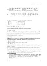
• Far from the antenna, the beam is high above the earth and can overshoot a
precipitating cloud. The rain may evaporate below the measurement height.
Orographical enhancement can occur.
• In cold winters, the difference between measurement height and surface can be 10 dB.
Vertical reflectivity profile correction can help to fix quantitative errors, but if there is
no measurement the correction does not help.
A.5 Doppler Wind Measurements
In comparison to non-Doppler radars, a Doppler radar can provide clutter cancellation and
wind products.
A Doppler radar measures the speed of the reflector by studying how the phase of
microwaves compared to the sent pulse changes between samples.
• A non-moving target has no phase shift.
• A target whose movement has no component in direction of the radar beam, has no
phase shift.
• A phase shift of exactly 2p looks like no phase shift.
• A phase shift of 2p+d looks like phase shift d.
• A phase shift of n*2p+d looks like phase shift d. This is called aliasing.
To get good Doppler measurements, many samples must be processed together (64 is
good). This sets limits to antenna speed.
The maximum speed which can be measured unambiguously is
V
max
= PRF × λ
4
where λ (lambda) denotes wavelength.
A.6 Clutter Cancellation
Clutter is defined as echoes from hills, buildings, masts, sea, and noise as marks in the image
caused by electronics of the equipment. The goal of clutter cancellation is to remove clutter
without destroying rain data.
To illustrate a Doppler filter we study speed spectra of a bin. That is, Doppler speed of each
sample, horizontal axis being speed (towards or away from radar, 0 in the middle). If all
samples indicate no speed we know the target is not moving. However, even antenna
movements gives some speed. And there are cases when it is raining at the hills.
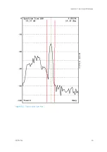
The next image shows a Doppler spectra from a bin, which contains clutter (speed near 0)
and rain moving toward the radar (big hump on the left) as well as some noise (small humps
everywhere, seen alone on the right). To find the right settings for the Doppler filter, we can
move the red lines closer to each other (less rain data is destroyed) or further from each
other (more clutter is canceled).
IRIS Product and Display User Guide
M211319EN-H
300
RESTRICTED
Содержание IRIS
Страница 1: ...M211319EN H RESTRICTED User Guide IRIS Radar IRIS Product and Display...
Страница 12: ...IRIS Product and Display User Guide M211319EN H 10 RESTRICTED...
Страница 71: ...Chapter 3 Configuring IRIS Products RESTRICTED 69...
Страница 294: ...To add icons you must include a text next to the icon IRIS Product and Display User Guide M211319EN H 292 RESTRICTED...
Страница 303: ...Figure 103 Typical Spectrum Plot Appendix A Basic Radar Meteorology RESTRICTED 301...
Страница 324: ...Figure 109 Example of Volume Rendering IRIS Product and Display User Guide M211319EN H 322 RESTRICTED...
Страница 329: ...C 8 Using the Product Information Tool Figure 113 Product Information Tool Appendix C IRIS 3DView RESTRICTED 327...
Страница 386: ......
Страница 392: ......
Страница 393: ......
Страница 394: ...www vaisala com...


