TOBY-L4 series - System Integration Manual
UBX-16024839 - R04
Design-in
Page 93 of 143
2.6.3
SPI interfaces
SPI interfaces are not supported by the "50" product version.
2.6.3.1
Guidelines for SPI circuit design
TOBY-L4 series modules include up to two 1.8 V Serial Peripheral Interfaces to communicate with external SPI
slave devices, with the module acting as SPI master, by means of the uCPU API.
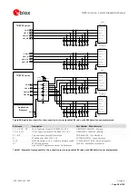
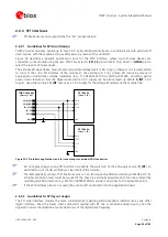
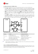
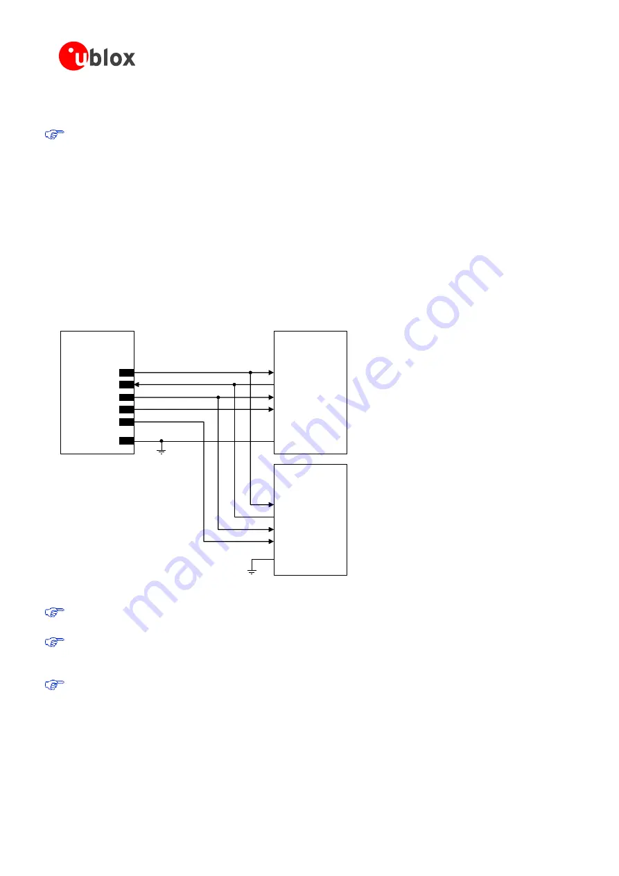
Figure 52 describes a possible application circuit for the SPI0 interface, where two SPI slave devices are
connected to the module using the two SPI0 Chip Select 0 (
SPI_CS
pin) and SPI0 Chip Select 1 (
GPIO4
pin) to
select the specific SPI slave device.
The external SPI slave device must provide compatible voltage levels (1.80 V typ.), otherwise it is recommended
to connect the 1.8 V SPI interface of the module to the external 3.0 V (or similar) SPI device by means of
appropriate unidirectional voltage translators (e.g. TI SN74AVC4T774 or SN74AVC2T245, providing partial
power down feature so that the digital audio device 3.0 V supply can be also ramped up before
V_INT
1.8 V
supply), using the module’s
V_INT
output as a 1.8 V supply for the voltage translators on the module side.
TOBY-L4 series
(Master, 1.8V)
SCLK
CS
MOSI
MISO
GND
SPI_SCLK
SPI_CS
SPI_MOSI
SPI_MISO
SPI Device
(Slave, 1.8V)
GND
SCLK
CS
MOSI
MISO
SPI Device
(Slave, 1.8V)
GND
GPIO4
Figure 52: SPI interface application circuit for connecting two external SPI slave devices
Do not apply voltage to any SPI interface pins before the switch-on of the SPI supply source (
V_INT
), to
avoid latch-up of circuits and allow a clean boot of the module.
The ESD sensitivity rating of SPI interfaces pins is 1 kV (Human Body Model according to JESD22-A114).
A higher protection level could be required if the lines are externally accessible and it can be achieved by
mounting an ESD protection (e.g. EPCOS CA05P4S14THSG varistor array) close to the accessible points.
If the SPI interfaces pins are not used, they can be left unconnected on the application board.
2.6.3.2
Guidelines for SPI layout design
The SPI serial interface requires the same considerations regarding electro-magnetic interference as any other
digital interface. Keep the traces short and avoid coupling with RF line or sensitive analog inputs, since the
signals can cause the radiation of some harmonics of the digital data frequency.

