TOBY-L4 series - System Integration Manual
UBX-16024839 - R04
Design-in
Page 107 of 143
2.8.1.2
Guidelines for analog audio downlink path circuit design
Guidelines for connecting an external low-power receiver / speaker
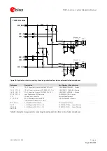
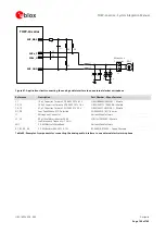
Figure 63 and Table 47 show an application circuit connecting the downlink path of the analog audio interface
of TOBY-L4 series modules to a low-power receiver / speaker:
A 16
receiver / speaker is connected to the analog audio downlink path of the module
As in the example circuit in Figure 63 and Table 47, the following general guidelines are recommended for the
design of an analog audio circuit connecting a low-power receiver / speaker:
Connect the
SPK_P
and
SPK_N
analog downlink outputs directly to the receiver / speaker (which resistance
rating must be greater than 14
).
Provide suitable parts on each line connected to the receiver / speaker as noise and EMI improvements, to
minimize RF coupling, according to EMC requirements of the custom application.
o
Mount a 27 pF bypass capacitor (e.g. Murata GRM1555C1H270J) from each speaker line to the solid
ground plane (C1 and C2 capacitors in Figure 63).
Provide additional ESD protection (e.g. Bourns CG0402MLE-18G varistor) if the analog audio lines will be
externally accessible on the application device, according to the EMC/ESD requirements of the custom
application. Mount the protection close to an accessible point of the line (D1 and D2 in Figure 63).
TOBY-L4 series
SPK_P
SPK_N
D1
C1
C2
SPK
Speaker
Connector
J1
D2
Figure 63: Application circuit connecting the analog audio interface to a low-power speaker
Reference
Description
Part Number – Manufacturer
C1, C2
27 pF Capacitor Ceramic C0G 0402 5% 25 V
GRM1555C1H270JA01 – Murata
D1, D2,
Low Capacitance ESD Protection
CG0402MLE-18G - Bourns
J1
Speaker Connector
Various Manufacturers
SPK
16
Speaker
Various Manufacturers
Table 47: Example of components for connecting the analog audio interface to a low-power speaker

