TOBY-L4 series - System Integration Manual
UBX-16024839 - R04
Design-in
Page 83 of 143
Guidelines for dual SIM card / chip connection
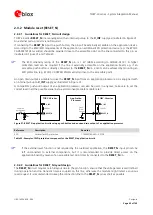
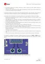
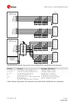
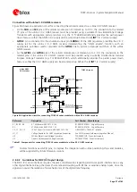
Two SIM cards / chips can be connected to the SIM interfaces of TOBY-L4 modules as illustrated in Figure 40.
TOBY-L4 series modules do not support the usage of two SIMs at the same time, but two SIMs can be populated
on the application board:
connecting the first SIM to the SIM0 interface of the module and connecting the second SIM to the SIM1
interface of the module, as illustrated in Figure 40 top side
In this case, the SIM interface and the related external SIM card / chip to be used can be selected by means
of the AT+XSIMSWITCH command (see
u-blox AT Commands Manual
[2]) or by means of uCPU application,
performing the SIM switch operation
providing a suitable switch to connect only the first or only the second SIM at a time to the SIM0 interface of
the module, as illustrated in Figure 40 bottom side
In this case, if the SIM hot insertion / removal feature is enabled on the
GPIO5
pin by AT commands (see
sections 1.8.2 and 1.13, and the
u-blox AT Commands Manual
[2], +UGPIOC, +UDCONF=50 commands) or
by means of uCPU application, than the switch from the first to the second external SIM can be properly
done when a Low logic level is present on the
GPIO5
pin (“SIM not inserted” = SIM interface not enabled),
without the necessity of a module re-boot, so that the SIM interface will be re-enabled by the module to use
the second SIM when a high logic level is re-applied on the
GPIO5
pin. The application processor will drive
the SIM switch using its own GPIO to properly select the SIM that is used by the module. Another GPIO may
be used to handle the SIM hot insertion / removal function of TOBY-L4 series modules, which can also be
handled by other external circuits or by the cellular module GPIO according to the application requirements.
The dual SIM connection circuit illustrated in Figure 40 can be implemented for SIM chips as well.
If it is required to switch between more than 2 SIMs, a circuit similar to the one illustrated in Figure 40 bottom
side can be implemented, using suitable switches.
Follow these guidelines to connect the module to two external UICC / SIM:
Connect the contact C1 (VCC) of the first external UICC / SIM to the
VSIM
pin of the module and the one
of the second external UICC / SIM to the
VSIM1
pin of the module.
Connect the contact C7 (I/O) of the first external UICC / SIM to the
SIM_IO
pin of the module and the one
of the second external UICC / SIM to the
SIM1_IO
pin of the module.
Connect the contact C3 (CLK) of the first external UICC / SIM to the
SIM_CLK
pin of the module and the
one of the second external UICC / SIM to the
SIM1_CLK
pin of the module.
Connect the contact C2 (RST) of the first external UICC / SIM to the
SIM_RST
pin of the module and the
one of the second external UICC / SIM to the
SIM1_RST
pin of the module.
Connect the contact C5 (GND) of each external UICC / SIM to ground.
Provide a 100 nF bypass capacitor (e.g. Murata GRM155R71C104K) at the SIM supply (
VSIM
/
VSIM1
),
close to the related pad of each external UICC / SIM, to prevent digital noise.
Provide a bypass capacitor of about 22 pF to 47 pF (e.g. Murata GRM1555C1H470J) on each SIM line, very
close to each related pad of each external SIM connector, to prevent RF coupling especially when the RF
antenna is placed closer than 10 - 30 cm from the SIM card holders.
Provide a very low capacitance (i.e. less than 10 pF) ESD protection (e.g. Tyco Electronics PESD0402-140) on
each externally accessible SIM line, close to each pad of each external SIM connector, according to the
EMC/ESD requirements of the custom application.
Limit the capacitance and series resistance on each SIM signal to match the SIM requirements (20.5 ns is the
maximum rise time on the clock line, 1.0 µs is the maximum rise time on the data and reset lines).
If a circuit as the one illustrated in Figure 40 bottom side is implemented, use a suitable low on resistance
(i.e. few ohms) and low on capacitance (i.e. few pF) 2-throw analog switch (e.g. Fairchild FSA2567) as SIM
switch to ensure high-speed data transfer according to SIM requirements.

