TOBY-L4 series - System Integration Manual
UBX-16024839 - R04
System description
Page 18 of 143
Function
Pin Name
Pin No
I/O
Description
Remarks
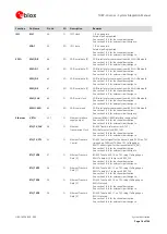
MMC_RST_N
211
O
Multi-Media Card
Reset
Embedded Multi-Media / SD Card memory reset.
See section 1.10 for functional description.
See section 2.7 for external circuit design-in.
MMC_CD_N
218
I
Multi-Media Card
Detect
Embedded Multi-Media / SD Card detect.
See section 1.10 for functional description.
See section 2.7 for external circuit design-in.
I2S0
I2S_TXD
51
O
I2S0 transmit data
I
2
S transmit data output.
See sections 1.11 for functional description.
See sections 2.8 for external circuit design-in.
I2S_RXD
53
I
I2S0 receive data
I
2
S receive data input.
See sections 1.11 for functional description.
See sections 2.8 for external circuit design-in.
I2S_CLK
52
I/O
I2S0 clock
I
2
S serial clock.
See sections 1.11 for functional description.
See sections 2.8 for external circuit design-in.
I2S_WA
50
I/O
I2S0 word alignment I
2
S word alignment.
See sections 1.11 for functional description.
See sections 2.8 for external circuit design-in.
I2S1
I2S1_TXD
206
O
I2S1 transmit data
I
2
S transmit data output.
See sections 1.11 for functional description.
See sections 2.8 for external circuit design-in.
I2S1_RXD
207
I
I2S1 receive data
I
2
S receive data input.
See sections 1.11 for functional description.
See sections 2.8 for external circuit design-in.
I2S1_CLK
208
I/O
I2S1 clock
I
2
S serial clock.
See sections 1.11 for functional description.
See sections 2.8 for external circuit design-in.
I2S1_WA
205
I/O
I2S1 word alignment I
2
S word alignment.
See sections 1.11 for functional description.
See sections 2.8 for external circuit design-in.
Analog
audio
MIC_BIAS
231
O
Microphone supply
output
Supply output for external microphones.
See sections 1.11 for functional description.
See sections 2.8 for external circuit design-in.
MIC_GND
230
I
Microphone analog
reference
Local ground for the external microphone.
See sections 1.11 for functional description.
See sections 2.8 for external circuit design-in.
MIC1_P
237
I
MIC1 differential
analog audio input (+)
MIC1 differential analog audio signal input (positive).
See sections 1.11 for functional description.
See sections 2.8 for external circuit design-in.
MIC1_N
236
I
MIC1 differential
analog audio input (–)
MIC1 differential analog audio signal input (negative).
See sections 1.11 for functional description.
See sections 2.8 for external circuit design-in.
MIC2_P
234
I
MIC2 differential
analog audio input (+)
MIC2 differential analog audio signal input (positive).
See sections 1.11 for functional description.
See sections 2.8 for external circuit design-in.
MIC2_N
233
I
MIC2 differential
analog audio input (–)
MIC2 differential analog audio signal input (negative).
See sections 1.11 for functional description.
See sections 2.8 for external circuit design-in.

