TOBY-L4 series - System Integration Manual
UBX-16024839 - R04
System description
Page 20 of 143
1.4
Operating modes
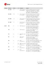
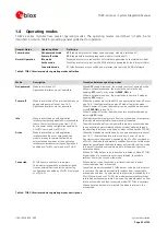
TOBY-L4 series modules have several operating modes. The operating modes are defined in Table 5 and
described in detail in Table 6, providing general guidelines for operation.
General Status
Operating Mode
Definition
Power-down
Not-powered mode
VCC
supply not present or below operating range: module is switched off.
Power-off mode
VCC
supply within operating range and module is switched off.
Normal Operation
Idle mode
Module processor core runs with 32 kHz reference generated by the internal oscillator.
Active mode
Module processor core runs with 26 MHz reference generated by the internal oscillator.
Connected mode
RF Tx/Rx data connection enabled and processor core runs with 26 MHz reference.
Table 5: TOBY-L4 series modules operating modes definition
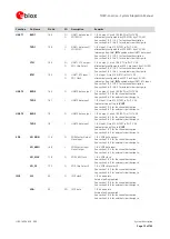
Mode
Description
Transition between operating modes
Not-powered
Module is switched off.
Application interfaces are not accessible.
When
VCC
supply is removed, the modules enter not-powered mode.
When in not-powered mode, the modules do not switch on by
applying
VCC
supply, or by using the
PWR_ON
pin.
When in not-powered mode, the modules go to power-off mode by
applying
VCC
supply.
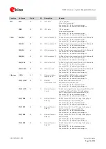
Power-off
Module is switched off: normal shutdown by an
appropriate power-off event (see 1.6.2).
Application interfaces are not accessible.
When the modules are switched off by an appropriate power-off event
(see 1.6.2), the modules enter power-off mode from active mode.
When in power-off mode, the modules can be switched on by means
of the
PWR_ON
pin (see 1.6.1).
When in power-off mode, the modules enter not-powered mode by
removing
VCC
supply.
Idle
Module is switched on with application
interfaces temporarily disabled or suspended to
reduce the current consumption (see 1.5.1.5)
due to power saving configuration enabled by
AT+UPSV command or uCPU API
The modules automatically switch from the active mode to low power
idle mode whenever possible if power saving is enabled.
The modules wake up from low power idle mode to active mode due
to any necessary network related activity, external wake-up through
the operating interfaces, or wake-up by means of dedicated uCPU API.
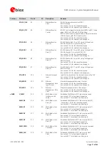
Active
Module is switched on with application
interfaces enabled or not suspended: the
module is ready to communicate with an
external device by means of the application
interfaces unless power saving configuration is
enabled by AT+UPSV command or uCPU API.
When the modules are switched on by an appropriate power-on event
(see 1.6.1), the module enter active mode from power-off mode.
If power saving configuration is enabled by the AT+UPSV command or
uCPU API, the module automatically switches from active to idle mode
whenever possible and the module wakes up from idle to active mode
in the events listed above (see idle mode to active mode transition
description above).
When a RF Tx/Rx data or voice connection is initiated or when RF Tx/Rx
is required due to a connection previously initiated, the module
switches from active to connected mode.
Connected
RF Tx/Rx data connection is in progress.
The module is prepared to accept data signals
from an external device unless power saving
configuration is enabled by AT+UPSV command
or uCPU API.
When a data or voice connection is initiated, the module enters
connected mode from active mode.
Connected mode is suspended if Tx/Rx data or voice is not in progress.
In such case, the module automatically switches from connected to
active mode and then, if power saving configuration is enabled by the
AT+UPSV command or uCPU API, the module automatically switches
to idle mode whenever possible. Vice-versa, the module wakes up from
idle to active mode and then connected mode if RF Tx/Rx is necessary.
When a data connection is terminated, the module returns to the
active mode.
Table 6: TOBY-L4 series modules operating modes descriptions

