Functional Description
29
ID: um_tsmux
CP525 cMux User’s Manual Rev. 5.20.12 (3944)
Alarms are graphically represented in a tree structure optimized for simplified individual view-
ing and configuration. The “Device Alarm” tree is available from the “Device Info” page. The
alarm tree for each port is available on the “Alarms” page for each port.
The alarm manager presents the alarm of highest severity upon the external interfaces of the
device. The severity level of each individual alarm can be defined by the administrator. Alarm
configuration is covered in greater detail in the “Alarm configuration” section.
SNMP traps are dispatched to registered receivers whenever there is an alarm status change.
Alarm relay 1 and alarm LED are controlled to signal whenever there is a
critical
alarm present.
Alarm relay 2 is configurable.
The alarm manager keeps a log in non-volatile memory of the latest 10000 alarms that have
occurred.
As an additional option, the alarm manager in the CP525 supports so-called
Virtual Alarm
Relays
. These are highly programmable items that can be customised to react to virtually any
given alarm event or combination of alarm events. The status of each virtual alarm relay can
be viewed in the GUI and can also be exported using SNMP. Details on configuring the virtual
alarm relays can be found in the WEB interface section.
5.8 Time synchronisation
The CP525 contains an internal real-time clock that is used for all internal timestamps. The
internal clock is battery backed up in order to continue operating while the unit has no power.
The internal time can be synchronised as follows:
•
Manual setting.
•
From one of the ASI/SMPTE 310M ports (using TDT/TOT or STT)
•
From NTP servers using SNTP protocol. Up to four NTP servers can be configured for
NTP server redundancy.
More than one clock source may be specified in a prioritised order. If one source fails the next
priority source will be used.
The internal clock can be used for generation of TDT/TOT on the output.
5.9 TSP Module
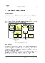
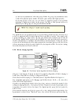
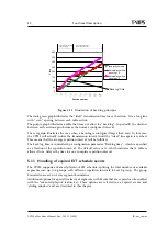
The TS Processor (TSP) module is the heart of the unit. Its job is to create a new MPEG Trans-
port Stream based on configuration and current input signals. Figure
shows the different
components in the TSP subsystem.
The lower left hand corner represents the interface between the management subsystem and
the TSP subsystem.
The central process in the TSP module is the TS Builder, which handles the logic creating PID
routing and regenerate PSI/SI/PSIP based on configuration and current PSI/SI/PSIP tables.
See
for more details on service and PID routing.
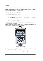
The following chapters covers more on the different modules shown in the figure.
Содержание CP525 cMux
Страница 1: ...CP525 cMux User s Manual Revision 5 20 12 3944 2012 12 17 Valid for SW version 5 20 12 and newer ...
Страница 2: ......
Страница 10: ......
Страница 12: ...12 CP525 cMux User s Manual Rev 5 20 12 3944 ID um_tsmux ...
Страница 18: ...18 CP525 cMux User s Manual Rev 5 20 12 3944 ID um_tsmux ...
Страница 24: ...24 CP525 cMux User s Manual Rev 5 20 12 3944 ID um_tsmux ...
Страница 66: ...66 CP525 cMux User s Manual Rev 5 20 12 3944 ID um_tsmux ...
Страница 238: ...238 CP525 cMux User s Manual Rev 5 20 12 3944 ID um_tsmux ...
Страница 248: ...248 CP525 cMux User s Manual Rev 5 20 12 3944 ID um_tsmux ...
Страница 276: ...276 CP525 cMux User s Manual Rev 5 20 12 3944 ID um_tsmux ...


