Forward Error Correction in IP Networks
271
ID: um_tsmux
CP525 cMux User’s Manual Rev. 5.20.12 (3944)
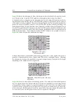
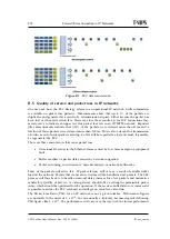
If more than one packet is lost in a row or a column of a matrix, the possibility to recover it
depends on packet location.
shows this.
Figure B.6
Uncorrectable error patterns
The red-coloured packets are lost in transmission. The pattern to the left normally results in 4
unrecoverable payload packets. However, if two of the lost packets are FEC packets, then only
2 payload packets will be lost. The pattern to the right will result in one lost payload packet.
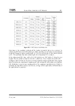
The specifications allow several parameter combinations for the FEC stream generation. The
FEC matrix sizes can in principle be chosen at will to suit the operational conditions. Operators
may easily be confused by the number of options, and it is not straightforward to choose the
optimal FEC setting for a given scenario. For compatibility reasons SMPTE 2022-1 specifies that
an MPEG-2 to IP network adapter should handle a minimum matrix size of 100 IP packets,
and that row length or column depth should not exceed 20. Also the shortest column length
allowed is 4.
B.4 Transmission aspects
The RTP protocol must be used if FEC shall be added to the IP payload. In order to provide
compatibility between equipment handling application layer FEC and equipment without that
capability FEC data is transmitted using UDP port numbers different from that of the payload.
Column FEC is transmitted using port number (IP payload) + 2 and row FEC (if used) is
transmitted using port number (IP payload) + 4.
Introducing FEC for the IP connection obviously leads to additional data overhead and conse-
quently a higher demand on data capacity. The generated FEC packets need to be "squeezed"
in between the payload packets, which will tend to increase the packet jitter experienced by the
receiver. Notably, in a rectangular matrix all column-FEC packets are generated and inserted
into the stream in succession. This leads to a short burst of packets in quick succession, or a
considerable delay before the first packet of the next FEC frame can be transmitted (or indeed,
some of each).
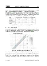
illustrates the relative timing of FEC packets and payload packets. Applying an
offset column structure results in a smoother packet stream. The overall packet rate will be the
same in both schemes, since the same number of FEC packets are generated, but the packets
will be more evenly spread in the IP stream. With larger matrix sizes the smoothing effect of
an offset matrix will even more pronounced. The effect of added overhead and jitter should
be considered when applying FEC to an IP video stream in a heavily loaded network. High
instantaneous packet rates may cause temporary overload resulting in packet loss, defeating the
object of introducing FEC in the first place.
Содержание CP525 cMux
Страница 1: ...CP525 cMux User s Manual Revision 5 20 12 3944 2012 12 17 Valid for SW version 5 20 12 and newer ...
Страница 2: ......
Страница 10: ......
Страница 12: ...12 CP525 cMux User s Manual Rev 5 20 12 3944 ID um_tsmux ...
Страница 18: ...18 CP525 cMux User s Manual Rev 5 20 12 3944 ID um_tsmux ...
Страница 24: ...24 CP525 cMux User s Manual Rev 5 20 12 3944 ID um_tsmux ...
Страница 66: ...66 CP525 cMux User s Manual Rev 5 20 12 3944 ID um_tsmux ...
Страница 238: ...238 CP525 cMux User s Manual Rev 5 20 12 3944 ID um_tsmux ...
Страница 248: ...248 CP525 cMux User s Manual Rev 5 20 12 3944 ID um_tsmux ...
Страница 276: ...276 CP525 cMux User s Manual Rev 5 20 12 3944 ID um_tsmux ...

