background image

D 86

D_DF1

1

5_135C_

G

B

.f

m

. 86-

92 -

 02-

01.

0

3

4.3

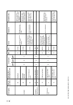
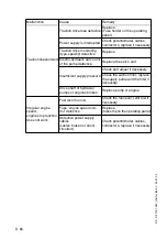
Malfunctions on the paver finisher or screed

Malfunction

Cause

Remedy

At the diesel engine Diverse

See operating instructions for 
the engine

Diesel engine does 
not start

Batteries empty

See ”External starting”


(start assistance)

Diverse

see ”Towing”

Tamper or vibration 
does not operate

Tamper is obstructed by 
cold bitumen

Properly heat the screed

Hydraulic oil level in the 
tank is too low

Top up the oil

Pressure limiting valve is 
defective

Replace the valve; if necessary, 
repair and adjust the valve

Leak in the suction line of 
the pump

Seal or replace the connections

Tighten or replace the hose 
clamps

Oil filter is soiled

Clean the filter; if necessary, 
replace the filter

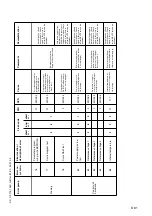
Conveyor or augers 
run too slowly

Hydraulic oil level in the 
tank is too low.

Top up the oil

Power supply is interrupted

Check fuses and cables; replace 
if necessary

Switch is defective

Replace the switch

One of the pressure limit-
ing valves is defective

Repair or exchange the valves

Pump shaft broken

Replace the pump

Limit switch does not switch 
or regulate correctly

Check the switch; replace and 
adjust the switch if necessary

Pump is defective

Check the high pressure filter for 
dirt particles; replace if necessary

Oil filter is soiled

Replace the filter

Hopper cannot be 
swung open

Engine speed is too low

Increase the speed

Hydraulic oil level is too low Top up the oil

Leak in the suction line

Tighten the connections

Flow rate regulator 
defective

Replace

Leaking seals of the 
hydraulic cylinder

Replace

Control valve is defective

Replace

Power supply interrupted

Check fuse and cables; replace 
if necessary

Содержание DF 115 C

Страница 1: ...Operating instructions 02 01 03 Road Finisher 900 98 06 40 DF 115 C DF 135 C...

Страница 2: ......

Страница 3: ...description applicable to the avail able option is used Safety information and important explanations are identified by the following picto grams Precedes safety information to be observed to prevent...

Страница 4: ......

Страница 5: ...ndard type 9 4 1 Performance data 9 4 2 Final drive track group 9 4 3 Engine 9 4 4 Hydraulic system 10 4 5 Hopper trough 10 4 6 Weights all values in t 10 4 7 Material feed 11 4 8 Material distributio...

Страница 6: ...oolant level too low error message 44 2 5 Remote control 45 Emergency program for TDM failure 48 2 6 Special functions 50 Reversible conveyor 50 2 7 Operating elements on the paver finisher 51 Batteri...

Страница 7: ...topping the finisher 67 Switching off and securing the finisher 67 3 4 Preparations for paving 68 Separating agent 68 Screed heater 68 Direction marks 68 Loading distributing material 69 3 5 Starting...

Страница 8: ...r every 100 operating hours 7 2 6 Monthly or every 250 operating hours 8 2 7 Every 3 months or every 500 operating hours 9 2 8 Annually or every 1000 operating hours 10 2 9 Every 2 years or every 2000...

Страница 9: ...Conveyor auger drive chains 4 5 29 Auger box 4 6 30 Outer auger bearing 4 7 31 Visual inspections 5 1 31 Crossbeam guide 5 2 31 Nuts and bolts 5 3 32 Tightening torques 32 Moving parts 5 4 32 Hydrauli...

Страница 10: ......

Страница 11: ...erator Operator in the sense of these operating instructions is any natural or judicial person who uses the road finisher himself or on whose behalf the machine is used In exceptional cases e g leasin...

Страница 12: ......

Страница 13: ...e description 1 Description of application The SVEDALA DEMAG road finisher is equipped with a crawler for laying bituminous material rolled or lean mixes concrete track ballast and uncombined mineral...

Страница 14: ...tor and trailing ski mount 4 Crawler 5 Levelling cylinder for laying thickness 6 Traction roller 7 Levelling arm draw bar 8 Laying thickness indicator 9 Levelling arm 10 Track drive 11 Spreader 12 Scr...

Страница 15: ...separate final drives 10 and clearly arranged control elements 15 Additional equipment Individual hopper control Electric refuelling pump Hydraulic spreader height adjustment Weather protection shed...

Страница 16: ...Push roller crosshead The push rollers for the material trucks are attached to a crosshead which is pivoted in the centre By means of the crosshead the varying distances to the rear wheels of the mat...

Страница 17: ...tion angle traction roller lift the laying thickness of the material or skimming level of the screed can be controlled Actuation takes place on both sides electro hydraulically and can take place eith...

Страница 18: ...ency button on operation panel on both remotes optional When the emergency button is pressed motor drives and steering are deactivat ed any necessary countermeasures such as manoeuvring screed lifting...

Страница 19: ...ower switch is located on the right hand side of the paver finisher between the central panel and hopper 3 6 Trough safety lock 3 7 Screed safety lock The screed safety locks are provided on both side...

Страница 20: ...03 3 8 Other safety devices Other equipment Wedges Warning triangle First aid box Item Designation 23 Engine covers 24 Side flaps 25 Catwalks 26 Screed covers 27 Material duct 28 Screed hazard lights...

Страница 21: ...min Laying thickness 300 mm Max Particle size 40 mm Theoretical laydown rate DF115C 600 t h Theoretical laydown rate DF135C 750 t h Drive Hydrostatic drive infinitely variable speed Track group Two i...

Страница 22: ...nal drive Material feed and distribution Tamper vibration optional Cylinder actuating elements for trough levelling screed lift screed extend retract Spreader lift optional Downstream compressor optio...

Страница 23: ...ht bar conveyor spreader halves switchable for operation in opposite directions Flow control Fully automatic via adjustable switching points Spreader lift mechanical via chain mechanical hydraulic opt...

Страница 24: ...with roof folded down 3000 C Min transport height without roof and tail pipe 2610 D Trough height trough fully closed 1600 E Operation panel height 1600 F Hopper length 2100 G Dumping 1950 H Distance...

Страница 25: ...F 82 2 dB A DF115C Sound capacity level LWA 106 2 dB A DF135C Sound capacity level LWA 106 6 dB A Sound pressure level at the machine 5 2 Operating conditions during measurements The diesel engine ope...

Страница 26: ...cab of ahw 2 5 m s according to the draft standard prEN 1033 1995 are not exceeded Emitted interference according to DIN EN 50081 1 03 93 40 dB V m for frequencies from 30 MHz 230 MHz at a measuring...

Страница 27: ...r 1 Open cylinder valves and main shut off valve Press hose protection for several seconds 2 Turn ignition key and switch on power supply with separate switch 3 Troubleshooting should be carried out o...

Страница 28: ...eck for diesel fuel 4 Sign Filler neck for hydraulic oil 5 Sign Close safety valve immediately 6 Sign Attention Standing in the operating area 7 Sign Check hydraulic oil level 8 Sign Hearing protectio...

Страница 29: ...r of manufacture 49 Serial number of finisher series 50 Maximum permissible operating weight including all extension sections in kg 51 Maximum possible load on front axle in kg 52 Maximum permissible...

Страница 30: ...2 Item Designation 55 Year of manufacture 56 Type of gas to be used 57 Inlet pressure in bar 58 Average gas consumption of mounted screed in kg h Liquefied petroleum gas system Year of manufacture Pr...

Страница 31: ...opper Close all coverings and check that they are securely seated In Germany gas bottles must not be transported on the paver finisher or on the screed Disconnect the gas bottles from the gas system a...

Страница 32: ...Extend the levelling cylinders com pletely by using key 4 in connection with the keys in the keyblock right Press button 5 Set the preselector 8 to zero Set the drive lever 9 to the center po sition R...

Страница 33: ...ger distances Secure the paver finisher to the low bed trailer Use only appropriate approved at tachment devices Use the four securing points provid ed 1 2 Wait until the exhaust extension tube has co...

Страница 34: ...ng key 4 in connection with the keys in the keyblock right Press button 5 Set the preselector 8 to zero Set the drive lever 9 to the center po sition Retract the screed parts until the screed matches...

Страница 35: ...ing on public roads Set the Fast Slow switch 12 to Hare Turn the preselector 8 to maximum Use the drive lever 9 to regulate the speed Press the emergency stop button when a dangerous situation arises...

Страница 36: ...finisher and render it safe Engage the transport safeguards Remove any attachments and acces sories from the paver finisher and the screed until the basic width has been attained Take off all protrud...

Страница 37: ...disconnect mechanism is only operated with the machine at a stand still Observe that dirt or other contaminants do not enter the gear drive Disengaging procedure Drain the oil by removing the drain p...

Страница 38: ...er al flaps with the screed raised i e when the crossbeams are in front of the lateral flaps these can be pushed to the side and removed Open both locks 1 Remove locking screw 2 Remove two mounting sc...

Страница 39: ...nnot dam age the vehicle Pull off the ignition key and the main switch 19 and take it with you do not hide them somewhere on the ma chine Protect the operating panel with the dust cover 20 and lock it...

Страница 40: ......

Страница 41: ...and limb Always make sure during operation that no one is endangered by the machine Ensure that all protective covers and hoods are fitted and secured accordingly When damages are detected eliminate...

Страница 42: ...D 2 D D_DF115_135C_GB fm 2 92 02 01 03 2 Operating elements 2 1 Operating panel 3 2 B C 1 A 4 C B A Bed_SPS_C2 tif Element1_SPSC cdr Element2_SPSC cdr Element3_SPSC cdr...

Страница 43: ...ht ahead refer to adjustment for straight ahead travel Forturningonthespot refertoswitch turningonthespot 2 Retaining bracket for operating panel For securing the movable operating panel against inadv...

Страница 44: ...D 4 D D_DF115_135C_GB fm 4 92 02 01 03 Element2_KC cdr 9 8 12 A 9 A 5 6 7 11 10...

Страница 45: ...the case of an emergency danger to persons possible col lision etc press in the button Pressing the emergency stop button switches off the engine the drives and the steering system Making way lifting...

Страница 46: ...D 6 D D_DF115_135C_GB fm 6 92 02 01 03 Element2_KC cdr 9 8 12 A 9 A 5 6 7 11 10...

Страница 47: ...set the maximum speed 10 Preselector trac tion drive For setting the maximum speed that can be reached when the drive lever is at its stop The scale roughly matches the speed in m min during paving 11...

Страница 48: ...D 8 D D_DF115_135C_GB fm 8 92 02 01 03 Element1_SPSC cdr B 25 26 28 22 21 30 31 15 16 27 29 23 20 24 32 13 17 18 19 33 14 34...

Страница 49: ...ing button with LED indication Operating requirements button 16 OFF Button 15 is used for the filling function The diesel engine speed is increased to the preselected nominal speed and all conveying f...

Страница 50: ...D 10 D D_DF115_135C_GB fm 10 92 02 01 03 Element1_SPSC cdr B 25 26 28 22 21 30 31 15 16 27 29 23 20 24 32 13 17 18 19 33 14 34...

Страница 51: ...on Button 17 is set to tortoise 19 Turning on the spot The finisher turns on the spot the caterpillar chains run in opposite directions when the steering knob 1 is set to 10 Steering knob turned to th...

Страница 52: ...D 12 D D_DF115_135C_GB fm 12 92 02 01 03 Element1_SPSC cdr B 25 26 28 22 21 30 31 15 16 27 29 23 20 24 32 13 17 18 19 33 14 34...

Страница 53: ...t and LED D right indicate the setting Switched off by pressing the button again or by pressing but ton 28 or 31 Adjustment of the levelling cylinders occurs by using the appro priatebuttoninthepad ri...

Страница 54: ...D 14 D D_DF115_135C_GB fm 14 92 02 01 03 Element1_SPSC cdr B 25 26 28 22 21 30 31 15 16 27 29 23 20 24 32 13 17 18 19 33 14 34...

Страница 55: ...ed to the direction of the arrow 29 Pad left for the directions of move ment Used in conjunction with buttons 25 28 and 31 releases a movement to the indicated direction 30 Horn Must be activated in t...

Страница 56: ...D 16 D D_DF115_135C_GB fm 16 92 02 01 03 Element1_SPSC cdr B 25 26 28 22 21 30 31 15 16 27 29 23 20 24 32 13 17 18 19 33 14 34...

Страница 57: ...sed the screed is lowered After releasing the button the screed is blocked again and the LED indicates OFF Button 16 is set to the OFF position During paving the screed must always be in the floating...

Страница 58: ...D 18 D D_DF115_135C_GB fm 18 92 02 01 03 Element3_SPSC cdr Kontrollleucht_SPSC cdr C 46 47 43 44 50 36 37 51 45 41 42 38 39 40 48 35 49...

Страница 59: ...on Escape closes the menu 36 Temperature indi catorforhydraulicoil Normal display up to 120 C 248 F Stop the paver finisher when higher temperatures are encountered drive lever 9 to the center positio...

Страница 60: ...D 20 D D_DF115_135C_GB fm 20 92 02 01 03 Element3_SPSC cdr Kontrollleucht_SPSC cdr C 46 47 43 44 50 36 37 51 45 41 42 38 39 40 48 35 49...

Страница 61: ...indica tor blue Lights up when the high beam is switched on at the ignition key 18 Avoid blinding the oncoming traffic 41 Not used 42 Not used 43 Coolant check red Lights up if the coolant level is to...

Страница 62: ...D 22 D D_DF115_135C_GB fm 22 92 02 01 03 Element3_SPSC cdr Kontrollleucht_SPSC cdr C 46 47 43 44 50 36 37 51 45 41 42 38 39 40 48 35 49...

Страница 63: ...wn automat ically still possible to process the paver finisher Stop paver finisher drive lever in central position leave en gine to cool at idling speed Determine cause and if necessary rectify refer...

Страница 64: ...fm 24 92 02 01 03 2 2 Operating the input and display terminal Display keyboard A Button Escape closes the menu B C Buttons Left right D F Buttons Scroll up down F Button Enter starts the menu operati...

Страница 65: ...screed stop and tamper start 4 Display showing various actual engine statuses 5 Service program for workshop and mechanics 6 Push button F to select one of the subordinates choose one of the subordin...

Страница 66: ...for each conveyor is shown in displays 1 and 2 Press button F to jump to the sub menu for setting the layer thickness Press button A to jump back to the main menu Paving depth One can choose out of t...

Страница 67: ...2 Two different operating hours values are displayed Total operating hours 1 with engine running Real operating hours 2 during installation In order to observe maintenance intervals chapter F call up...

Страница 68: ...ing the buttons D E Confirm the value required by pressing the button F number no longer flashes The menu sub item can be exited by pressing the button A Select the Sub menu symbol 6 and confirm by pr...

Страница 69: ...d The nominal value for the tamper start dynamics 6 can be set in the range of be tween 0 and 100 Nominal specification is 50 Delayed tamper start The nominal value for the tamper start dynamics 7 can...

Страница 70: ...on 1 automatic steering unit activated If the appropriate equipment Sonic Ski is fitted the finisher can independently travel along a reference body e g securing rope when the automatic steering unit...

Страница 71: ...ror messages are not to be called up exit the menu item by pressing the button A To call up the messages use button C to call up the selection window 2 make selection with button F and press the butto...

Страница 72: ...tion in L h 3 Battery voltage 4 Select the Sub menu symbol 6 and confirm by pressing button F to jump into the Counter showing distance travelled sub menu Counter showing distance travelled The counte...

Страница 73: ...ructed personal is authorized for the further proceedings Return to the basic menu by pressing push button A By pressing the F button the follow ing screed is called up and the pro grammable controlle...

Страница 74: ...s up when pressing push button 21 of the operating panel RPM speed of the engine is displayed graphically The present fuel consumption is also displayed in l h Stop Comes up in the case of emergency b...

Страница 75: ...this menu by pressing push button F The following information is given Example Pos Description 1 the part affected and its function 2 electrical malfunction 3 matching PLC module 4 controlled element...

Страница 76: ...36 92 02 01 03 Variations of malfunction Pos 2 Variations Pos 4 Meaning Graphic Parting of cable Short circuit Meaning Graphic Ultrasound sensor mechanical limit switch Potentiometer Valve Electronics...

Страница 77: ...ing Auger L H lowering Auger R H lifting Auger R H lowering Levelling L H lifting Levelling L H lowering Levelling R H lifting Levelling R H lowering Hopper L H open Hopper L H close Hopper R H open H...

Страница 78: ...evant fuse example F250 6 This should be checked first before initi ating any other measures Meaning Graphic Screed stop Tamper function Vibration function Left remote control Right remote control Scr...

Страница 79: ...Example Malfunction of the auger R H lower ing Short circuit of the valve Y35B at the PLC module A2 Terminal strip X1 cable clamp 65 colour of the cable green red Abbr Meaning bl blue br brown ge yel...

Страница 80: ...s failed Data connection with the master module is interrupted First check whether fuse F5 1 is still intact If the fuse has not caused the interrupt to thedataconnection thedieselenginecan be started...

Страница 81: ...teway EMR Error in engine electronics EMR Battery Potential to low Travelling speed Potentiometer defective Drive lever Potentiometer defective Steering potentiometer Potentiometer defective Sensor RP...

Страница 82: ...ed Travelling motion Backward blocked Travelling motion Turning left blocked Travelling motion Turning right blocked Travelling motion Forward backward blocked Screed warning light Parting of cable or...

Страница 83: ...ode ENGINE WARNING display 2 is displayed if there is a less serious error and the warning light 1 is permanently lit up STOP ENGINE display 3 is displayed if there is a serious error and an engine st...

Страница 84: ...ossible engine shutdown if the engine protec tion shutdown function is activated Frequency This error has now occurred three times Inform the After Sales Service for your paver finisher of the error n...

Страница 85: ...D 45 D D_DF115_135C_GB fm 45 92 02 01 03 2 5 Remote control 63 55 59 60 54 SPSRemote Tif 61 56 58 65 64 62 57...

Страница 86: ...itching state manual 58 Buttons for direc tions of movement Functionsinsamewayasbuttons 27 onoperatingpanel 59 Conveyor Functions in same way as button 32 on operating panel 60 Adjuster for the capaci...

Страница 87: ...levelling unit Connect the cable for the grade control unit here 67 Socket for auger limit switch Connect the cable for the material limit switch here 68 Cable for the remote control Connect the plug...

Страница 88: ...revolutions of the Diesel engine 2100 min 1 Traction drive 1 slow Turtle Operating main switch 2 OFF Tamper 3 switched on Vibration 4 switched on Connected functions will not be indicat ed by LED dur...

Страница 89: ...infinitely variable by using the both Minus buttons 4 simultaneous Switching the screed into readiness floating position Switch the LED bar 3 of auger and conveyor completely on by using the accompany...

Страница 90: ...erefore be avoided Switch main function switch 16 over to Off switch position LED off Hold down one or both of the buttons 32 in the STOP switch position for approx 5 seconds The system jumps into the...

Страница 91: ...the finisher externally see section Starting the paver finisher External starting starting aid Battery main switch 72 Located on the right side between the front wall and trough is the battery switch...

Страница 92: ...ransport safe guard to the left and the right be neath the driver s seat 74 Used to protect the lifted screed from in advertent lowering The screed transport safeguard must be inserted before trans po...

Страница 93: ...ey must be locked The seats must not protrude from the ve hicle during transportation Push the seats back to the basic width of the paver finisher Pull out the locking button and move the seat let the...

Страница 94: ...diesel engine is running other wise the battery will be discharged Switch off after use Don t spray into open flame or on hot surface Danger of explosion Locking of the collapsible roof LH and RH on...

Страница 95: ...itches 88 or the ultrasonic conveyor limit switches 89 control the material flow at the respective conveyor half The con veyors should stop when the material has roughly reached the area below the aug...

Страница 96: ...e connected to the re mote control units located at the sides of the screed We recommend to adjust the limit switch positions while the material is distributed Sockets for the remote control left and...

Страница 97: ...ed to adjust the pressure for screed stop with pretensioning Activation see screed charging re lieving device 44 Pressure display see manometer 93b Manometerforscreedcharging reliev ingandscreedstopwi...

Страница 98: ...arts that may become necessary for extending the auger Parts that may become necessary for extending the screed Percentage spirit level and levelling rail 4 m long Levelling wire Protective clothing s...

Страница 99: ...he horn button The horn must sound Lights Switch on with the ignition key walk around the paver finisher to check and switch off again Hazard warning lights of the screed with vario screeds With the i...

Страница 100: ...nsport safeguard When the screed is lifted it must be possible to push the locking rods side ways into the recesses in the cross beams using the lever beneath the seat Hopper transport safeguard Whent...

Страница 101: ...s and protective devices Normal starting Setthedrivelever 9 tothecenterposition and the speed adjuster 10 to minimum Insert the ignition key 5 in position 0 The lights should be switched off during st...

Страница 102: ...ine Switch on the ignition set the drive le ver 9 to the center position Use appropriate cables to connect the external power source Observe the polarity Always connect the negative cable last anddisc...

Страница 103: ...lever 9 to position 1 slightly off the center position Increase the engine speed by press ing button 21 on the operating panel The engine speed will be increased to the preselected value Let the pave...

Страница 104: ...ns Oil pressure indicator lamp for the diesel engine 45 Must go out right after the engine is started Pull out the ignition key immediately to switch off the engine if the lamp does not go out or ligh...

Страница 105: ...raulics warm up until the in dicator lamp goes out The lamp goes out when the pressure drops below 2 8 bar 40 psi For further possible malfunctions refer to section 4 Battery charge indicator 47 Must...

Страница 106: ...buttons 34 and lift the screed full by using button 33 Extend the levelling cylinders full by using the buttons 25 and 27 The remote control has to be connect ed and the same function has to be set to...

Страница 107: ...rection desired In case of an emergency press the emergency stop button 7 To stop the finisher set the drive lever 9 to the center position Switching off and securing the finisher Turn the ignition ke...

Страница 108: ...e screed heater ca 15 30 minutes depending on the ambient temp erature before paving begins Warming up prevents the material from sticking to the screed plates See the section 3 3 on how to operate th...

Страница 109: ...button 15 to fill the machine for paving Switch the conveyors on The limit switches for the conveyors 89 or 89a must switch off when the material has reached the area be neath the auger crossbeam Chec...

Страница 110: ...D 70 D D_DF115_135C_GB fm 70 92 02 01 03 3 5 Starting for paving Element1_SPSC cdr Element2_SPSC cdr Tamprev cdr Vibrev cdr SPSRemote Tif 20 32 33 17 10 9 51 54 56 B A 23 24...

Страница 111: ...ect if nec essary Carry out the check in the area of the drive chains or wheels as the screed tends to level an uneven ground The reference points for the layer thickness are the drive chains or wheel...

Страница 112: ...esareintheway Uniform material transport and distribution or supply to the screed may require cor rections to settings of the material switches for conveyor and auger See the section Malfunctions when...

Страница 113: ...increases the traction force Charging increases the screed weight reduces the traction force but increases the compaction ratio To be used with light weight screeds in exceptional cases Screed chargi...

Страница 114: ...nto the freshly laid material thus supporting the screed stop function especially in those situation where the screed relieving function is used The pressure to be applied depends on the load bearing...

Страница 115: ...e and read it from the manometer 93b Basic setting 20 bar For screed charging relieving Set the drive lever 9 to the center po sition Set switch 16 to position LED OFF and switch 21 to position LED ON...

Страница 116: ...eate an edge like the end of a layer Set the drive lever 9 to the center po sition During extended interruptions Drive lever 9 into centre position RPM speed adjustment 10 to minimum position Switch o...

Страница 117: ...eed letanymaterialresiduesdropout Set the drive lever 9 to the center po sition and the speed adjuster 10 to minimum Switch off the ignition 5 Switch off screed heater system When screed is operated w...

Страница 118: ...eck the operating hour meter to determine whether mainte nance work must be performed see chapter F Cover and lock the operating panel Remove material residues from the screed and the paver finisher a...

Страница 119: ...nsor 2 is available Emergency shutdown if sensor 2 is not available or has failed Check distance Check cable connection Check sensor and replace if nec essary 02 Speed sensor 2 2 1 2 8 190 Controller...

Страница 120: ...r linkage fuel injection pump replace if nec essary Check actuator cable Hardware inputs outputs 67 Error Hand Setp1 2 6 2 11 91 68 Error CAN Setp1 2 898 Communica tion 70 CAN bus controller 2 7 1 12...

Страница 121: ...within permis sible range Error message disap pears once power returns to normal range Switch ignition off and back on again Check again If error occurs inform DEUTZ service de partment 83 Reference v...

Страница 122: ...f and back on again Check again If error occurs inform DEUTZ service de partment 93 Stack overflow 2 SID 240 Internal computing error commonly referred to as Stack overflow error Emergency shutdown En...

Страница 123: ...ature has again fallen below recovery threshold After a delay period has passed filling limit Check charged air Check charged air temperature sensor and cable 34 Coolant level warning 2 3 5 1 111 Cool...

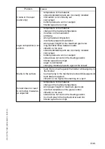
Страница 124: ...dmixing roller has stopped on the hot material rollerhasturnedorrollerspeedhasbeenchangedtoofast incorrect operation of the roller incorrectly prepared foundation truck brake is applied too tight long...

Страница 125: ...ncorrectly installed cold screed bottom plates are worn or warped screed does not work in the floating position finisher speed is too high auger is overloaded changing material pressure against the sc...

Страница 126: ...r Conveyor or augers run too slowly Hydraulic oil level in the tank is too low Top up the oil Power supply is interrupted Check fuses and cables replace if necessary Switch is defective Replace the sw...

Страница 127: ...tion Power supply is interrupted Check fuse and cables replace if necessary Crossbeams cannot be lifted or lowered Switch on the remote con trol is set to auto Set the switch to manual Power supply is...

Страница 128: ...Replace the servo unit Insufficient supply pressure Check and adjust if necessary Check the suction filter replace the supply pump and the filter if necessary Drive shaft of hydraulic pumps or engines...

Страница 129: ...l plugs of the drive pump servo valves have to be replaced by the plugs of the emergency device short screw driver is necessary The cable shoe is connected to power supply of 24 Volts and the cable ey...

Страница 130: ...turning knob 122 to a low speed Push switch 121 to the recommended direction and engage the forward reverse lever to forward direction If the recommended direction is reverse push switch 22 in reverse...

Страница 131: ...D 91 D D_DF115_135C_GB fm 91 92 02 01 03 Steering unit Servo valves Black Grey Grey Black Pump for right crawler Pump for left crawler Ground 24 V...

Страница 132: ......

Страница 133: ...ve ignition key and battery switch Mechanically secure raised machine components e g screed or trough against lowering Change spare parts properly or have them changed When connecting or disconnecting...

Страница 134: ...ow In the case of large operating widths tendency towards separation and traction problems Spreader too low Insufficient amount of material compacted by the spreader Resulting unevenness cannot be com...

Страница 135: ...orresponds 2 4 Spreader enlargement Depending on the particular type of screed diverse operating widths can be achieved The spreader and screed enlargement must correspond See also the chapter Setting...

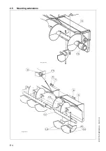
Страница 136: ...E 4 E DF 115 135C GB 4 6 02 01 03 2 5 Mounting extensions 16 5 9 10 8 7 6 5 14 12 11 15 12 Sch_ver1 tif Sch_ver2 tif...

Страница 137: ...ent Fix spreader wing 12 with screw 13 washer 14 and nut 15 to the spreader extension and simultaneously tightly screw the spreader shafts together If the operating conditions on the construction site...

Страница 138: ...fter mounting and adjustment of the mechanical assemblies the following connections must be established 4 1 Connect remotes to socket 17 at the screed 4 2 Connect grade transmitter to socket 18 at rem...

Страница 139: ...l parts and change them properly When in doubt con sult the manufacturer Re commissioning Before re commissioning mount all protective devices properly Cleaning Never carry out cleaning with the engin...

Страница 140: ...1 8 Engine mounting 1 9 Hoses and hose connections 1 10 Fuel tank 2 Hydraulic system 2 1 Hydraulic tank 2 2 Main filter return flow filter 2 3 Oil cooler 2 4 High pressure hydraulic filter 2 5 Hydrau...

Страница 141: ...F 3 F F_DF115_135C_GB fm 3 40 02 01 03 5 Miscellaneous 5 1 Visual inspection 5 2 Crossbeam guide 5 3 Nuts and bolts 5 4 Moving parts 6 Electrical system 6 1 Batteries Pos Maintenance location...

Страница 142: ...tank Change main filter 2 4 High pressure filter Change main filter 3 1 Track groups Check tension 3 2 Conveyor drive transmission Change oil 4 1 Conveyor chain Check tension 4 4 Planetary gear Auger...

Страница 143: ...intenance point Maintenance work 1 2 Engine lubricating oil Check oil level 1 4 Air filter Check function clean 1 5 Water cooler Check fluid level 2 1 Hydraulic tank Check oil level 2 4 High pressure...

Страница 144: ...rk 1 1 Pump distributor gear Check oil level and refill if necessary 1 6 Fuel filter Check and if necessary drain water 4 3 Flight bar conveyor gear Check oil level and refill if necessary 5 2 Side ba...

Страница 145: ...hydraulics Check function clean maintenance according to engine manufacturer s documentation 3 1 Track groups Check tension 4 1 Conveyor chain Check tension 4 4 Planetary gear Spreader Check oil level...

Страница 146: ...operating hours Item Maintenance point Maintenance work 1 8 Engine suspensions Check 3 2 Conveyor drive transmission Check oil level 4 6 Auger box Check oil level 1 1 4 4 2 1 2 4 3 1 3 2 4 1 4 5 4 6 4...

Страница 147: ...ting oil Change oil 1 3 Oil filter cups Change filter cartridge 2 1 Hydraulic tank Clean filling and vent filter 5 3 Nuts and bolts Check all operating relevant nuts and bolts for tightness and retigh...

Страница 148: ...ssary replace 1 9 Hoses and screw connections Check replace if necessary 2 2 Hydraulic tank Change main filter 2 5 Hydraulic cylinder Lubrication 3 2 Conveyor drive transmission Change oil 4 3 Planeta...

Страница 149: ...rs Item Maintenance point Maintenance work 1 4 Air filter Change safety cartridge 1 5 Water cooler Replace coolant 1 7 Fan and alternator belt Replace belt 2 1 Hydraulic tank Change oil 1 1 4 4 2 1 2...

Страница 150: ...y Item Maintenance point Maintenance work 3 2 Conveyor drive trans mission Refill oil 1 10 Fuel tank Drain water and sediment 3 3 Idler Check and refill oil 1 1 4 4 2 1 2 4 3 1 3 2 4 1 4 5 4 6 4 7 4 2...

Страница 151: ...seal cap of oil drain point 3 and screw on hose provided in accessories Place end of hose in collection container Use a wrench to open the shutoff valve and allow all oil to drain out Close shutoff va...

Страница 152: ...change should take place at op erating temperature Unscrew seal cap of oil drain point 1 and screw on hose provided in acces sories Place end of hose in collection con tainer Use a wrench to open shut...

Страница 153: ...y moving upwards Collect any oil which escapes Change paper filter cartridge 3 Clean any dirt which has accumulated from sealing faces of filter carrier 1 and guide 4 Replace rubber gasket 2 and oil i...

Страница 154: ...ilter housing 1 Take out filter cover 5 and remove fil ter cartridge 6 Clean filter cartridge or if necessary replace Cleaning filter cartridge Use dry compressed air max 5 bar to blow out from inside...

Страница 155: ...n opening Hydraulic cooler The finisher is fitted with a hydraulic oil cooler as standard This cooler is of de cisive importance for the operating relia bility of the complete hydraulic system A foule...

Страница 156: ...onics re port an error message Replacing upstream filter filter cartridge Drain off separated water Pull connector off water sensor 5 Use a filter wrench or filter belt to loos en the filter cartridge...

Страница 157: ...oil Carefully place new paper filter car tridge 8 in guide 9 Screw down fuel filter cover 6 turn clockwise 25 Nm Once the fuel filter has been fitted during the test ensure good sealing Once the new...

Страница 158: ...uld be replaced Observe engine s operating instructions Hoses and screw connections 1 9 Check all hoses on engine and all hy draulic hoses specifically for damage and correct fixture Replace any damag...

Страница 159: ...Fuel tank 1 10 To drain water and sediment Provide collecting container Unscrew drain screw 87 Drain about 1 l fuel into the collecting container Collected fuel must be disposed off in accordance with...

Страница 160: ...s 3 Remove cover 4 Remove filter 5 Fit new filter Renew gasket 6 and O ring 7 Refit cover 4 Close cover by tightening nuts 3 Oil change Retract piston rods of hydraulic cylin ders Fit hose over the dr...

Страница 161: ...g Fit new filter element Renew gasket at filter housing Loosely screw filter housing manually and tighten with a wrench Start trial run and check filter for leaks The gasket must be changed each time...

Страница 162: ...he track group with the engine switched off Unscrew screws 1 Remove cover 2 Screw head piece for flat nipple tool box to the grease gun Inject grease into the chain tensioner with the grease gun until...

Страница 163: ...below the bottom edge of the filling hole Retighten filling screw 1 To change oil Turn conveyor drive transmission so that the oil max mark is horizontal and drain screw 2 is located at the bottom Uns...

Страница 164: ...ten sioner at the lubricating nipple 1 on the left and right with the grease gun until the necessary chain tension is reached Do not tension chains one sided Center conveyor bearing 4 2 The grease nip...

Страница 165: ...before start of work The oil level must reach the top notch of the dipstick 1 Top up oil Through oil filler neck 3 once seal cover 2 has been removed 10 cm on the dipstick corresponds to around 0 25 l...

Страница 166: ...ling screw 2 Pour prescribed oil into filling hole 2 until the oil is just below the bottom edge of the check hole 1 Tighten filling 2 and check screw 1 To change oil The oil change should take place...

Страница 167: ...nce work on the drive chains with the engine switched off To retension the chains Loosen fixing screws 1 Adjust correct chain tension with screws 2 Tighten threading dowels with a torque wrench to 20...

Страница 168: ...again Change oil The oil change should take place at op erating temperature Place a suitable collecting container under the auger box Loosen screws 4 from circumference of worm shaft flange The oil ru...

Страница 169: ...1 Inspect the diesel engine for oil and fuel patches and fouling Inspect the complete hydraulic system pumps motors and cylinders for damage and leaks Check tension and lubrication of the drive chain...

Страница 170: ...ic screw connections noting point 1 9 until seal integrity is en sured Avoid skin coming into contact with hydraulic oil Preload N Tightening torque Nm Preload N Tightening torque Nm Preload N Tighten...

Страница 171: ...F 33 F F_DF115_135C_GB fm 33 40 02 01 03 Battery 6 1 The zero maintenance batteries can be found under the right hand lateral flap Check cable connections securing pin grease Bat115 jpg 32...

Страница 172: ...ase auger outer bearing Norva HT2 Hot bearing grease Unirex S2 Aeroshell Grease 22 Engine oil See engine operating instructions SAE 15W40 API CF 4 is filled in the factory Hydraulic oil See section 3...

Страница 173: ...ils When changing over from mineral oil to biodegradable oils please cotact the advice service of our company Use only clean containers inside and outside for filling in oil or fuel Manufacturer ISO c...

Страница 174: ...Conveyor chain gear per side Gear oil 220 1 5 litre Auger box Gear oil 460 2 5 litre Planetary gear Augers each side Gear oil 90 0 5 litre Coolant 40 antifreeze 18 litre Clamping cylinder on travellin...

Страница 175: ...BB3 1 3 Starter 10 4 Heater 10 5 1st electrical outlet rear left 10 6 2nd electrical outlet rear left scale illumination 10 7 1st electrical outlet rear right 10 8 2nd electrical outlet rear right sca...

Страница 176: ...MERGENCY STOP 5 2 Indicator lamps 3 3 Control module A1 display voltage converter Conveyor controller 10 4 Back up fuse Slave 1 3 10 5 Back up fuse Slave 4 6 10 6 Roof mounted headlight 10 7 Remote co...

Страница 177: ...39 40 02 01 03 Fuse box 4 No F2 1 F2 8 A 1 not in use 5 2 Horn 3 3 Windscreen wiper 3 4 not in use 7 5 5 Headlight front right 3 6 Headlamp front left fittings lighting 3 7 not in use 3 8 not in use 3...

Страница 178: ......

Отзывы: