


B 10
B DF
1
15/
135C.
G
B 1
0
-1
8 -
0
2
-0
1
.03
4.4
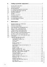
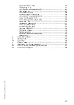
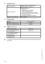
Hydraulic system
4.5
Hopper (trough)
4.6
Weights
(all values in t)
For weights of the respective screeds and screed sections, see operating instructions
for screeds.
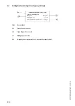
Pressure generation
Hydraulic pumps via distribution gear
(directly flanged on to engine)
Pressure distribution
Hydraulic circuits for:
-Final drive
-Material feed and distribution
- Tamper/vibration (optional)
- Cylinder actuating elements for trough,
levelling, screed lift, screed extend/retract,
Spreader lift (optional)
- Downstream compressor (optional)
Hydraulic oil tank capacity
(see Chapter F)
Capacity
ca. 6 m³ = about 13 t
Minimum inlet height, centre
480 mm
Minimum inlet height, external
600 mm
Finisher without screed
about 14,0 t
- Finisher with screed EB 50
(incl. side plates
about 17,6 t
- With extension sections for
max. Operating width
- additional max.
- With filled trough
additional max.
Содержание DF 115 C
Страница 1: ...Operating instructions 02 01 03 Road Finisher 900 98 06 40 DF 115 C DF 135 C...
Страница 2: ......
Страница 4: ......
Страница 10: ......
Страница 12: ......
Страница 40: ......
Страница 44: ...D 4 D D_DF115_135C_GB fm 4 92 02 01 03 Element2_KC cdr 9 8 12 A 9 A 5 6 7 11 10...
Страница 46: ...D 6 D D_DF115_135C_GB fm 6 92 02 01 03 Element2_KC cdr 9 8 12 A 9 A 5 6 7 11 10...
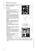
Страница 85: ...D 45 D D_DF115_135C_GB fm 45 92 02 01 03 2 5 Remote control 63 55 59 60 54 SPSRemote Tif 61 56 58 65 64 62 57...
Страница 132: ......
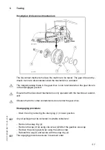
Страница 136: ...E 4 E DF 115 135C GB 4 6 02 01 03 2 5 Mounting extensions 16 5 9 10 8 7 6 5 14 12 11 15 12 Sch_ver1 tif Sch_ver2 tif...
Страница 178: ......