Engine Mechanical: 1D-38
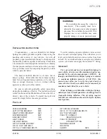
3) Release special tool, and remove spring retainers
and valve springs.
4) Remove valve from combustion chamber side.
5) Remove valve stem seal (1) from valve guide, and
then valve spring seat (2).
NOTE
Do not reuse seal once disassembled. Be
sure to use new seal when assembling.
6) Using special tool (Valve guide remover), drive valve
guide out from combustion chamber side to valve
spring side.
Special tool
(A): 09916–46020
NOTE
Do not reuse valve guide once disassembled.
Be sure to use new valve guide (oversize)
when assembling.
7) Place disassembled parts except valve stem seal
and valve guide in order so that they can be installed
in their original positions.
Reassembly
1) Before installing valve guide into cylinder head, ream
guide hole with special tool (11 mm reamer) so as to
remove burrs and make it truly round.
Special tool
(A): 09916–34542
(B): 09916–38210
2) Install valve guide to cylinder head.
Heat cylinder head uniformly at a temperature of 80
to 100
°
C (176 to 212
°
F) so that head will not be
distorted, and drive new valve guide into hole with
special tools.
Drive in new valve guide until special tool (Valve
guide installer) contacts cylinder head.
After installing, make sure that valve guide protrudes
by specified value from cylinder head.
Special tool
(A): 09916–57350
(B): 09916–57340
NOTE
• Do not reuse valve guide once
disassembled. Install new valve guide
(Oversize).
• Intake and exhaust valve guides are
identical.
Valve guide oversize
0.03 mm (0.0012 in.)
Valve guide protrusion “a”
In: 14.5 mm (0.57 in.)
Ex: 13.5 mm (0.53 in.)
I2RH01140125-01
I2RH01140126-01
I2RH01140127-01
I2RH01140128-01
Содержание 2006 SX4
Страница 2: ......
Страница 6: ......
Страница 22: ...00 15 Precautions...
Страница 38: ...0B 7 Maintenance and Lubrication...
Страница 378: ...1K 6 Exhaust System...
Страница 848: ...6C 46 Power Assisted Steering System...
Страница 954: ...7B 89 Air Conditioning System Automatic Type...
Страница 1086: ...8B 121 Air Bag System...
Страница 1381: ...Paint Coatings 9L 7 I5RW0C9C0005 01 A Apply sealant 1 Hole...
Страница 1382: ...9L 8 Paint Coatings I5RW0C9C0006 01 A Apply sealant covering flange end...
Страница 1386: ...9L 12 Paint Coatings I5RW0A9C0010 01 A Apply rust proof wax hot wax 50 m or more B Never fill up drain holes with rust proof wax...
Страница 1476: ...Prepared by 1st Ed Feb 2007...
Страница 1477: ...31 0 mm 99500 80J00 01E SERVICE MANUAL VOL 1 OF 2 99500 80J00 01E SERVICE MANUAL VOLUME 1 OF 2 RW420...
Страница 1478: ...28 0 mm 99500 80J00 01E SERVICE MANUAL VOL 2 OF 2 99500 80J00 01E SERVICE MANUAL VOLUME 2 OF 2 RW420...


