Chapter 5: Advanced Serverboard Setup
5-11
5-10
SUPERSERVER 8048B-TRFT USER'S MANUAL
5-5 Installing Memory
Caution:
exercise extreme care when installing or removing DIMMs to prevent any
possible damage. DIMMs should be installed with the memory card removed from
the baseboard. See the tables on page 5-12 for details on populating RDIMM/LDIMM
memory.
Installing Memory
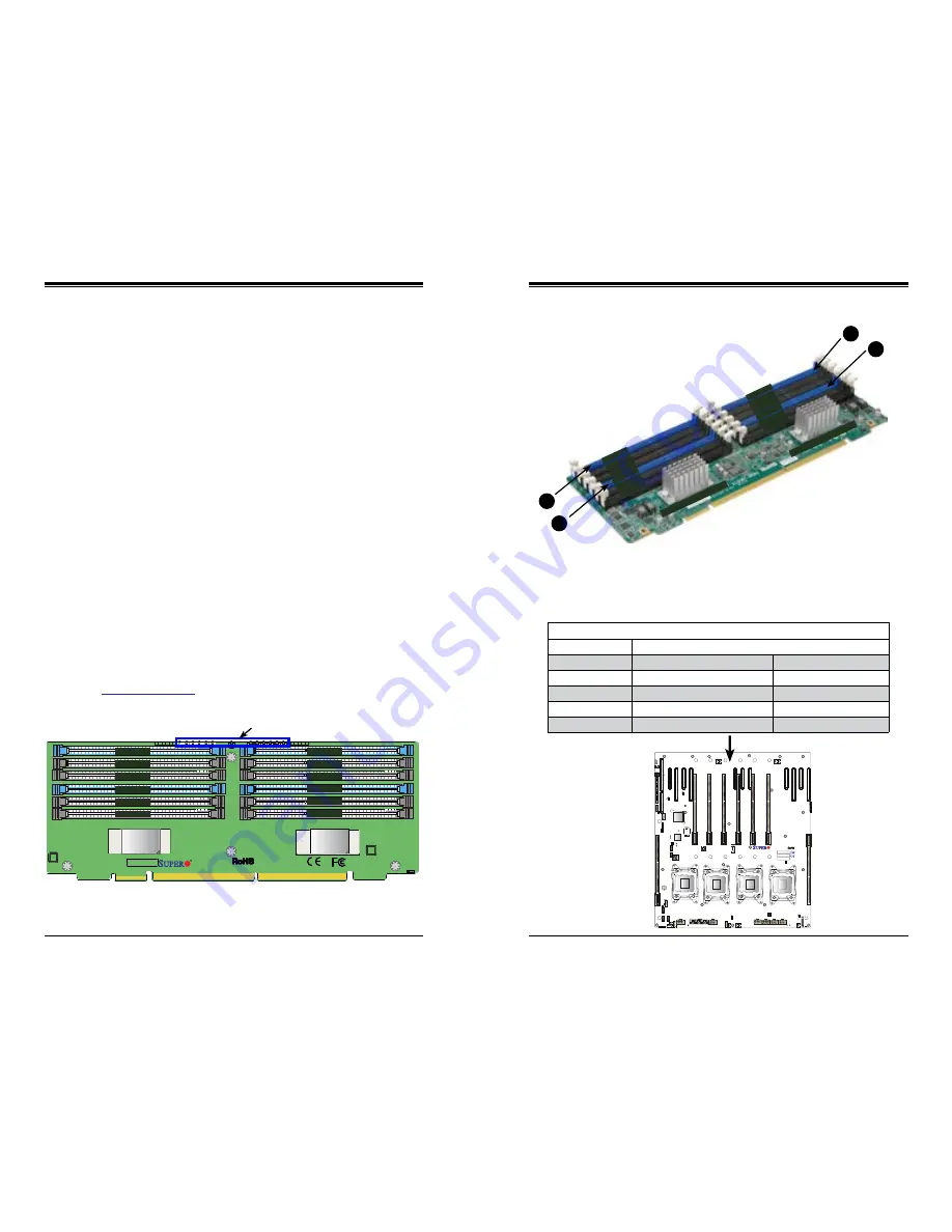
Insert the desired number of DIMMs into the slots on a memory card in the order
shown in Figure 5-4. For best performance, use the memory modules of the same
type and speed.
1. Push the release tabs outwards on both ends of the DIMM slot to unlock it.
2. Align the key of the DIMM module with the receptive point on the memory
slot.
3. Press both ends of the module straight down into the slot until the module
snaps into place.
4. Press the release tabs to the locking positions to secure the DIMM module
into the slot.
5. Reverse the steps above to remove DIMM modules.
Memory Support
With all eight cards fully populated, the system will support up to a total of 6 TB of
DDR3-1600/1333/1066/800 ECC RDIMM/LDIMM memory. Check the Supermicro
website (
www.supermicro.com
) for the latest memory support information.
Figure 5-4. X10QBi-MEM1 Memory Card Layout
Figure 5-5. X10QBi-MEM1 Memory Card Image
X10QBi-MEM1
PRESENT_LED1
DIMM2A_LED3
DIMM1A_LED2
DIMM0A_LED1
DIMM2B_LED6
DIMM1B_LED5
DIMM0B_LED4
DIMM2C_LED1
DIMM1C_LED8
DIMM0C_LED7
DIMM2D_LED4
DIMM1D_LED3
DIMM0D_LED2
BAR CODE
A3
D1
D2
C1
C2
C3
D3
OK
B1
B2
B3
A1
A2
JDI
JDI
DIMMC3
DIMMA1
DIMMA2
DIMMA3
DIMMB3
DIMMB2
DIMMB1
Rev. 1.01
DIMMC2
DIMMC1
DIMMD3
DIMMD2
DIMMD1
DIMM C3
DIMM C2
DIMM C1
DIMM D3
DIMM D2
DIMM D1
DIMM A3
DIMM A2
DIMM A1
DIMM B3
DIMM B2
DIMM B1
PRESENT LEDs
Notes
:
When installing a DIMM module, be sure to press the module straight down
into the slot until it is properly seated and its PRESENT LED (as shown above)
turns on.
DIMM A3
DIMM A2
DIMM A1
DIMM B3
DIMM B2
DIMM B1
2
1
3
4
DIMM C3
DIMM C2
DIMM C1
DIMM D3
DIMM D2
DIMM D1
Memory Buffer Controller
Memory Buffer Controller
Always install DIMMs in
the blue slots first (in
order of DIMMA1, DIMMB1,
DIMMC1, and DIMMD1).
X10QBi
Rev:1.00
MAC CODE
BAR CODE
MAC CODE
SMI Slot P1M1 (for CPU1)
SMI Slot P1M2 (for CPU1)
SMI Slot P2M1 (for CPU2)
SMI Slot P2M2 (for CPU2)
SMI Slot P3M1 (for CPU3)
SMI Slot P3M2 (for CPU3)
SMI Slot P4M1 (for CPU4)
SMI Slot P4M2 (for CPU4)
After populating DIMMs on the memory cards, follow the table below to Install one
or two populated memory cards for each CPU installed on the baseboard. The
baseboard has eight slots to accommodate eight memory cards.
CPUs and their Corresponding Memory Cards
CPU#
Corresponding DIMM Modules
One Memory Card Per CPU
Two Memory Cards Per CPU
CPU 1
SMI Slot P1M1 (populate this slot first)
SMI Slot P1M1 + SMI Slot P1M2
CPU 2
SMI Slot P2M1 (populate this slot first)
SMI Slot P2M1 + SMI Slot P2M2
CPU 3
SMI Slot P3M1 (populate this slot first)
SMI Slot P3M1 + SMI Slot P3M2
CPU 4
SMI Slot P4M1 (populate this slot first)
SMI Slot P4M1 + SMI Slot P4M2
Slots for Memory Cards
Содержание SuperServer 8048B-TRFT
Страница 1: ...USER S MANUAL Revision 1 0a SuperServer 8048B TRFT...
Страница 15: ...2 10 SUPERSERVER 8048B TRFT USER S MANUAL Notes...
Страница 29: ...4 20 SUPERSERVER 8048B TRFT USER S MANUAL Notes...
Страница 46: ...5 32 SUPERSERVER 8048B TRFT USER S MANUAL Notes...
Страница 52: ...6 10 SUPERSERVER 8048B TRFT USER S MANUAL Notes...
Страница 79: ...7 52 SUPERSERVER 8048B TRFT USER S MANUAL Notes...
Страница 81: ...A 2 SUPERSERVER 8048B TRFT USER S MANUAL Notes...


