Sunny Island 4500
Installation & Operating Instructions
BWRI45-13-EE0304
- 44 -
SMA Regelsysteme GmbH
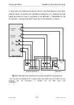
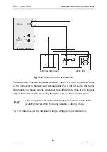
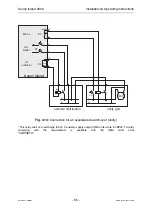
Due to galvanic isolation between the battery and grid side within the Sunny Island it
is basically possible – but not necessary – to ground the minus or plus pole of the
battery externally. In this case make sure that the very high currents that can occur
for a short time in case of an error are discharged as well.
We cannot make general recommendations for the dimensioning of the required
grounding cable as this considerably depends on the type of battery used, the exter-
nal fused interrupter and the design of the incoming cables of the battery.
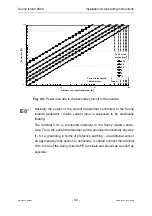
If an additional grounding cable with a larger cross-section is required this can be
connected to the M6 threaded hole (marked as such) on the aluminum backplane
(heat sink) of the Sunny Island.
The required cable cross-section of the grounding conductor can be es-
timated with the following formula for fused interrupters with disconnect-
ing times up to 5 s if a copper cable is used:
S =
(I
SC
2
∗
t)
143
t = disconnecting time in seconds, I
SC
= maximum battery current (short-circuit current)
in amperes, S = conductor cross-section in mm²
The maximum battery current can be seen in the data sheets for the bat-
tery. If this is not possible it can usually be estimated with the following
formula:
I
SC
=
C
0,05h
C = battery capacity in Ah
For an exact determination of the grounding conductor cross-section please refer to
the relevant standards (e. g. VDE 0100 part 540).

