Sunny Island 4500
Installation & Operating Instructions
BWRI45-13-EE0304
- 43 -
SMA Regelsysteme GmbH
3.4 Examples for Connection
In the following chapters you can read about the possibilities how to connect the in-
verter to its environment. Examples for the different connection types are provided.
How to wire the components and the Sunny Island for protective
grounding depends on the type of grid installed and can therefore
differ. Therefore, the figures below do not show any PE-wiring /
grounding. Of course, the entire cabling must be installed in compli-
ance with all relevant standards and regulations.
Furthermore, to allow different kinds of grounding concepts the
Sunny Island’s N-terminal is NOT connected to PE by default. Thus,
any required connection between N and PE has to be performed ex-
ternally. Due to EMI-measures the voltage of the AC terminals will be
round about symmetrically to PE without any further wiring.
3.4.1 Connection to Ground
Due to filtering measures within the Sunny Island increased leakage currents to PE
can occur during operation. Therefore make sure the inverter is firmly grounded ac-
cording to DIN EN50178.
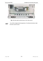
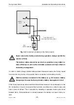
To this end the inverter can be grounded at the ground terminals in
the terminal area either with one single copper conductor of a mini-
mum 10 mm² cross-section or with two separate copper conductors
with cross-sections corresponding at least to the respective AC con-
ductor.
If the two ground conductors are not part of the AC connection cable
they should have a minimum cross-section of 4 mm² each.

