Sunny Island 4500
Installation & Operating Instructions
BWRI45-13-EE0304
- 69 -
SMA Regelsysteme GmbH
3.7.2 Multiple Connection at COM2 Interface
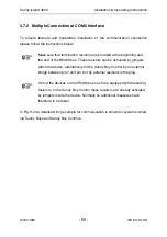
To ensure fail-safe and troublefree installation of the communication connection
please follow the instructions below:
Make sure that termination resistors are provided at the beginning and
the end of the RS485 bus. These resistors can be activated by jumpers
within the device, alternatively for the Sunny Boy Control by an external
bridge between pin 7 and pin 9 or by external resistors in the plug.
One of the devices on the RS485 bus has to be equipped with balancing
resistors. In the Sunny Boy Control these resistors are already activated
by jumpers inside the device. Normally no additional measures have
therefore to be taken.
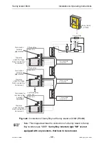
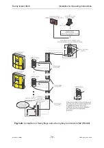
In Fig. 3.23 a detailed wiring example for communication is shown for systems includ-
ing Sunny Boys and Sunny Boy Controls.

