background image

Sunny Island 

Installation and Operating Instructions 

BWRI45-13:EE0304 

- 216 - 

SMA Regelsysteme GmbH


Name Unit 

Min. 

Max. 

Default 

Description 

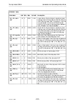
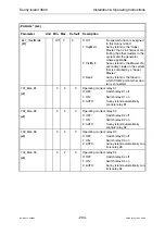
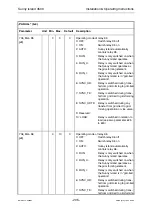
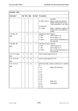
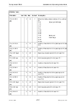
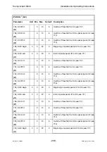
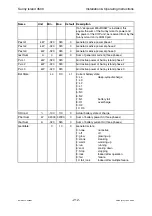
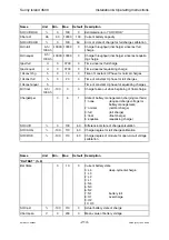
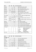
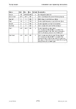
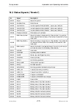
Sconv 

VA 

-32000  32000

Grid apparent power SI 

Sconv Sum 

kVA 

-320 

320 

Sum of grid apparent power SI (three phases) 

Uext eff 

500 

RMS value of synchronous voltage  

Fext 

Hz 

100 

Current grid frequency on synchronous input  

Iext eff 

500 

Current generator current (of converter) 

Iext Sum 

640 

Sum of generator current (three phases) 

Pext 

kW 

-320 

320 

Current generator active power  
If an “ecopower Mini-BHKW” is installed, this 
equals the power of the CHP unit, as received 
from by the Sunny Island on its COM3 port. 

Pext Sum 

kW 

-320 

320 

Sum of generator active power (three phases) 
If an “ecopower Mini-BHKW” is installed, this 
equals the sum of the Sunny Island’s power and 
the power of the CHP unit, as received from by the 
Sunny Island on its COM3 port. 

Содержание Sunny Island 4500

Страница 1: ...Bi directional Battery Inverter SI4500 for Stand alone Applications Sunny Island 4500 Installation Operating Instructions ...

Страница 2: ......

Страница 3: ...BWRI45 13 EE0304 Bi directional Battery Inverter SI4500 for Stand alone Applications Version 3 1 Installation Operating Instructions Sunny Island ...

Страница 4: ...d type of alteration 1 Comments Author 13 EE5103 3 0 A C Compilation and enhancement of SI3300 documentation for SI4500 Sabban 13 EE0304 3 1 A Minor changes of layout Salisbury 1 A Changes due to faulty documents or improvement of the documentation B Changes maintaining full or upward compatibility C Changes limiting or excluding compatibility ...

Страница 5: ...se note the following description of symbols This indicates a feature that is important either for optimal and comfortable usage or optimal operation of the system Example To keep string voltage low we recommend the following proce dure This indicates a fact or feature which is very important for the safety of the user and or which can cause a serious defect if not applied appropriately Example Di...

Страница 6: ...8 2 1 3 Droop mode operation RUN_U RUN_UEXT 19 2 1 4 Overload Behavior 21 2 2 Battery Management 23 2 2 1 Charging Methods 24 2 2 2 Battery States 26 2 2 3 Low Battery Load Mode 29 2 2 4 Failure of Individual Cells 30 3 Installation 31 3 1 Mounting Accessories Included in Delivery 31 3 2 Placement of the Sunny Island 33 3 3 Electric Connection 38 3 3 1 Preparing the Connection 38 3 3 2 Cable Conne...

Страница 7: ...d utility 62 3 5 Finalization of Electrical Wiring 63 3 6 Interfaces for Communication 64 3 6 1 Assignment of COM1 Interface Three Phase Operation 65 3 6 2 Assignment of COM2 Interface 66 3 7 Connection with Sunny Boy and Sunny Boy Control 67 3 7 1 Simple Connection at COM2 Interface 67 3 7 2 Multiple Connection at COM2 Interface 69 3 7 3 Simple Connection to PC 71 3 7 4 Alternative Communication ...

Страница 8: ...enerator 101 7 3 Menu FUNCT 2 3 Special Functions 104 7 4 Menu BHKW 2 5 ecopower support 105 8 Settings SETUP 107 8 1 Menu SETTIM 3 1 Setting the System Clock 108 8 2 Menu PASSWD 3 2 Entry of Password 109 8 3 Menu PARSYS 3 3 Parameters System 110 8 4 Menu PARGRD 3 4 Parameters Grid 112 8 5 Menu PARBAT 3 5 Parameters Battery 114 8 6 Menu PARGEN 3 6 Parameters Generator 117 8 7 Menu PARREL 3 7 Param...

Страница 9: ...tem with Photovoltaics 154 11 4 Mains Backup System with Generator and PV 157 11 5 Integrating CHP Units 161 11 6 Multiple Sunny Island Systems w Data interchange 165 11 6 1 Single Phase System 165 11 6 2 Three Phase System 169 11 7 Multiple Sunny Island Systems w o Data interchange 172 11 7 1 Single Phase System 173 11 7 2 Three Phase System 173 11 7 3 Mixed Single Three Phase Systems 174 12 Term...

Страница 10: ...I45 13 EE0304 8 SMA Regelsysteme GmbH 17 Measured Values Displayed Overview 211 18 Error and Status Signals 217 18 1 Error Signals 217 18 2 Status Signals Events 219 19 Declaration of Conformity 222 20 Contact 223 21 List of Figures 224 22 List of Tables 228 ...

Страница 11: ...ter may only be opened installed and ser viced by qualified personnel The device can still be charged with very high hazardous voltages even when disconnected Please closely follow all steps as described in this document when working on the inverter All safety instructions and all appropriate technical and local regulations must be followed ...

Страница 12: ...tivate electrolyte pumps and even battery room fans a controller providing a high level energy management including loadman agement and interaction with power sources like generators or photovoltaic in verters a universal generator management system with capability to start pre heat cool down etc combustion engines and even to control dedicated CHPs Combined Heat and Power units a modularly expand...

Страница 13: ... the general safety instructions described in Chapter 1 3 have to be observed at any rate This is both installer s guide and user manual so it is used as reference for the com missioning and as guideline on how to use all functions of the inverter optimally 1 Sunny Sunny Family Sunny Island and Sunny Boy are registered trademarks of SMA Regelsysteme GmbH Germany All other trademarks used in this d...

Страница 14: ...ons considers the features for the Sunny Island SI4500 with firmware BFR 2 00 DSP 2 00 and higher 1 2 What to do in case of transport damages Our products are thoroughly checked before they are shipped Even though they are delivered in sturdy packaging which can be recycled the inverters can be damaged in transit which is usually the forwarder s fault Please inspect your inverter thoroughly after ...

Страница 15: ...n mounting and wiring the storage battery risk of short circuit As a precaution against injuries wear suitable clothes for handling heavy and bulky devices when mounting and removing the Sunny Island such as working gloves and safety shoes The device may only be opened installed and serviced by a qualified electrician Even when disconnected there can be high touch volt ages within the device Pleas...

Страница 16: ...Island can work in different operating modes A short overview is given in Chapter 2 1 An outstanding feature of the Sunny Island is its capability to take care of the con nected lead storage battery Highly sophisticated charging algorithms assure a maximum lifetime of the battery A quick abstract of the battery management is given in Chapter 2 2 Although the first commissioning of stand alone syst...

Страница 17: ... voltage and frequency in the island grid Operation of the Sunny Island is based on the following operating modes Grid forming RUN_U the Sunny Island keeps the voltage and the frequency of the grid at a constant level Grid tied RUN_I the Sunny Island complies with the voltage and frequency that is defined by an additional component of the island grid that itself forms the grid Droop mode special k...

Страница 18: ... grid controlled power generators or consumers Consumers 230 V 50 Hz 60 Hz Fig 2 1 Sunny Island as grid forming element This operating mode requires that there are no further components within the grid that control the frequency or the voltage Parallel operation with the public utility or an independent synchronous generator is not possible in this mode In this mode the Sunny Island can only charg...

Страница 19: ...ries can therefore only be manipulated by controlling the power generating components and the consumers within the grid Due to the battery management the Sunny Island can perform a full charge of high quality even in this operating mode This might take several days if necessary for example if there are only photovoltaic feeders ...

Страница 20: ...nt synchronous generator or the public utility In this case the Sunny Island does not control the grid voltage and grid frequency but controls the current it draws from the grid to charge the battery in a defined and most suitable manner Sunny Island Control of battery current and battery voltage Control of frequency and voltage Sunny Boy PV Modules Consumers Generator as grid forming element SG 2...

Страница 21: ...ny respects similarly to the large public electric util ity Fig 2 3 Frequency vs load characteristics If the available power on the AC bus of the system is higher than the power de manded all Sunny Islands will charge their batteries and let the AC frequency slightly rise analog to the amount of energy stored in their batteries If the available power is less than the power demanded the missing amo...

Страница 22: ...an average cos φ of 1 will be reached Temporarily it will deviate from this value In such systems further grid forming elements e g gensets can only then be con nected if these are capable of automatically synchronizing themselves to the grid and have a droop characteristic However for some common system structures the Sunny Island provides functions to synchronize the system to the genset even in...

Страница 23: ... the fifteen fold nominal power when they are turned on These consumers do not continuously require this high power Therefore the Sunny Island does not have to be capable of generating this power What is more important is a sophisticated control strategy When such loads are connected the Sunny Island therefore reduces the AC voltage for a short time This not only reduces the current peaks on the A...

Страница 24: ... power In the overload area up to the limit mentioned above the Sunny Island thermally lim its the power This means that the device depending on the ambient temperature previous load and level of overload can provide the power for several minutes or even hours before the device is derated or switched off Another limiting element is the DC breaker F1 that might trip also depending on the ambient te...

Страница 25: ...ny Island has to be the only device in the system that is connected to the battery directly External devices connected to the battery e g DC loads or battery chargers will lead to a faulty battery management This will not only result in wrong battery states and associated erroneous switching op erations but also in an incorrect estimation of the battery s condition and thus to a significant reduct...

Страница 26: ...rmined via a battery temperature sensor Above 20 C the reference value for the final charge voltage is therefore decreased by 4 mV K visible in the menu PARBAT 3 5 Below 20 C the value is increased accordingly The Sunny Island is capable of running four different charging methods The different voltage values and charging times of those methods are adjusted with temperature compensation to the resp...

Страница 27: ...n the charging degree has fallen below 70 The pri ority is a short run time of an additional aggregate e g diesel generator By default a full charge is completed every two weeks or 8 charge throughputs A full charge leads to complete charging of the battery in order to avoid irreversible aging due to low charge degrees An equalizing charge is initiated every 180 days or 30 charge throughputs preve...

Страница 28: ... tion These are e g the battery voltage during overcharging or exhaustive discharg ing but also the times after a full charge or an equalizing charge has first been re quested The battery state therefore shows that either the availability of the energy stored deteriorates considerably due to the decreasing state of charge or the battery is in an area with increasing aging while its state of charge...

Страница 29: ...us state For example in a new system the battery state will initially be set to L1 and will not change until a normal charge has been completed After wards it will be set to N1 immediately Of course in such cases all switching operations of the relays will be executed as if the intermediate states were perambulated Battery states Description L4 L3 L2 L1 Reduced availability of the battery and incr...

Страница 30: ...power N3 Normal secu rity of supply Either reduce consumption or make sure battery is charged soon Switch on genset soon or switch off certain load groups N4 Low security of supply Either reduce consumption drastically or make sure battery is charged soon Switch on genset also at night or switch off all load groups that are not urgently required L1 Increasing ag ing Reduce consumption except for e...

Страница 31: ... g during the night but will still be fully active during the rest of the day This special time period can be defined with parameters 533_Stdby t beg and 534_Stdby t end cf Fig 8 14 in Chapter 8 7 Step 2 In all battery states below the one defined by parameter 535_State StopT the Sunny Island will be in standby mode day and night but will run in intervals of four hours for five minutes during dayt...

Страница 32: ...ells however must always be advised to the battery management of the Sunny Island by changing the parameter 503_Ubat nom in the menu PARBAT 3 5 accordingly Of course in systems with a nominal battery voltage of 48 V this removal of single cells is not possible as 48 V are already the least possible value for the Sunny Island The failure of individual cells should always be taken as a clear signal ...

Страница 33: ...ollow the general safety instructions Chapter 1 3 3 1 Mounting Accessories Included in Delivery Please find below the components ensuring easy mounting and installation of the Sunny Island which are included in delivery 1 Installation Operating Instructions which you are reading here 1 Bracket for recommended mounting to wall Fig 3 1 4 PG 13 5 glands incl nuts 4 PG 13 5 blank screwed joints 3 PG 1...

Страница 34: ...nd or SI BATCASE 03 for connection of up to three Sunny Islands Three phase synchronization cable connection between the different Sunny Islands in three phase operation SMA order code SI Synckabel Set Plug in relay to switch loads or start stop diesel generator etc SMA order code SI BPRE NO type resp SI BPRE OE NC type 24 V auxiliary supply output port for special plant interconnections see Chapt...

Страница 35: ... criteria are meant to help you decide where to position the Sunny Island Criteria for placement Installation only possible indoors due to protection degree IP20 Do not expose the inverter to direct or indirect humidity Keep cables leading to the battery storage as short as possible DC cabling Avoid installing in the living area as slight noise emission is possible Avoid mounting on resonant parts...

Страница 36: ... sioning so that any moisture condensation that might have oc curred can evaporate A minimum clearance of 20 cm must be available above the Sunny Island for ventilation i e no installation in cabinets with out ventilation no installation directly under ceiling etc The free air circulation around the case must not be obstructed to ensure sufficient cooling If you install the Sunny Island in a cabin...

Страница 37: ...cient size We recommend two 6 mm hexagon head screws and 8 mm wall anchors for fastening see Fig 3 1 Make sure the mounting bracket is securely fastened as it carries the Sunny Islands total weight After fastening and checking the secure position of the mounting bracket the Sunny Is land is hung into the intended strap on the mounting bracket and positioned with the correct orientation To prevent ...

Страница 38: ...Sunny Island 4500 Installation Operating Instructions BWRI45 13 EE0304 36 SMA Regelsysteme GmbH Fig 3 1 Mounting bracket with fastening points ...

Страница 39: ...Sunny Island 4500 Installation Operating Instructions BWRI45 13 EE0304 37 SMA Regelsysteme GmbH Fig 3 2 Side view of the Sunny Island with dimensions ...

Страница 40: ...id of the inverter s lower part To this end remove the two hexagon socket screws M5 accessible from the front Inside the lid there is a tab and receptacle connector with a green yellow grounding cable PE Carefully disconnect this connector After finishing the installation reconnect it Make sure the two automatic circuit breakers F1 and F2 are switched off After removing the two fastening screws th...

Страница 41: ...5 13 EE0304 39 SMA Regelsysteme GmbH Batt Temp K1 K2 K3 K4 K5 K6 K7 K8 Generator Mains I U N L 86 00741 Fig 3 3 Cable glands and terminals of the Sunny Island You will find a diagram with designations of the different terminals inside the lower case lid as well ...

Страница 42: ... Terminals for generator contactor via relay K2 Terminals for grid contactor via relay K3 Terminals for additional switchable components such as wind energy convert ers ohmic inductive loads via relays K1 to K8 freely configurable Terminals for battery room fan via relay K7 Terminals for battery acid circulation via relay K8 If the relays K1 K2 K7 and K8 are not used for their special tasks they c...

Страница 43: ...nerator Mains sync input K1 14 K1 13 K2 14 K2 13 K3 14 K3 13 K4 14 K4 13 K5 14 K5 13 K6 14 K6 13 control relay K7 Battery fan control relay K8 Battery circulation control relay K1 Generator start control relay K2 Generator contactor control relay K3 Mains control relay K4 SI contactor control relay K5 Syncswit operate load control relay K6 Gen crank operate load PE PE Chassis Earth Chassis Earth P...

Страница 44: ... SI contactor Relay K4 special functions are described in detail in Table 8 5 K5 14 K5 13 Relay K5 Syncsw oper ate load Relay K5 special functions are described in detail in Table 8 5 K6 14 K6 13 Relay K6 Gen crank op erate load Relay K6 special functions are described in detail in Table 8 5 K7 14 K7 13 Relay K7 Battery fan Relay K7 special functions are described in detail in Table 8 5 K8 14 K8 1...

Страница 45: ...ny Island s N terminal is NOT connected to PE by default Thus any required connection between N and PE has to be performed ex ternally Due to EMI measures the voltage of the AC terminals will be round about symmetrically to PE without any further wiring 3 4 1 Connection to Ground Due to filtering measures within the Sunny Island increased leakage currents to PE can occur during operation Therefore...

Страница 46: ...y If an additional grounding cable with a larger cross section is required this can be connected to the M6 threaded hole marked as such on the aluminum backplane heat sink of the Sunny Island The required cable cross section of the grounding conductor can be es timated with the following formula for fused interrupters with disconnect ing times up to 5 s if a copper cable is used S ISC 2 t 143 t di...

Страница 47: ... battery is to be grounded please follow the special instructions in Chapter 3 4 1 We urgently recommend a fused interrupter to disconnect the Sunny Island If there is no line protection fuse the installation of DC ca bles has to be inherently ground fault proof and short circuit proof The internal DC fuses of the Sunny Island are designed for interrupt ing currents of up to 20 kA for R L 0 015 s ...

Страница 48: ...e effect on the battery management In order to obtain always reliable battery related measured values the Sunny Island has to be the only device in the system that is connected to the battery directly External devices connected to the battery e g DC loads or battery chargers will cause the Sunny Island s battery management to fail If the Sunny Island was ordered with terminal blocks instead of cir...

Страница 49: ...ng to terminal X1 5 This terminal is connected to the case and thus to the PE connections of the inverter Therefore make absolutely sure to avoid creating any electric bond by attaching the temperature sensor to the battery 1 2 3 4 5 Sunny Island X1 PT 100 Battery temperature Fig 3 6 Connection of a temperature sensor To protect the battery always connect a battery temperature sensor the Sunny Isl...

Страница 50: ...external distribution is recommended G L N Sunny Island N L F2 or External distribution Direct consumer 6 A 6 A AC Outlet Fig 3 7 AC voltage connection Fig 3 7 shows an exemplary layout of a sub distribution if additional electric circuits and grid feeding devices are integrated into the system To allow different kinds of grounding concepts the Sunny Island s N terminal is NOT connected to PE by d...

Страница 51: ... shown in Fig 3 8 Sunny Island L N k k L L X2 1 2 3 4 N L I I 1 2 G L N PE Generator Mains Generator Mains sync input current input Fig 3 8 Connection of generator current and voltage measurement 1 Fuses for the protection of the generator voltage sensor cables 2 Current transformer Ensure sufficient fusing of the generator voltage sensor cables The cross section of the cable leading from the curr...

Страница 52: ...er Basically the output of the current transformer connected to the Sunny Island s generator mains current input is supposed to be electrically floating The terminal X2 1 is connected internally to the Sunny Island s enclo sure Thus the current transformer will be grounded functionally anyway If for a grounding in terms of protective earthing an additional wire of an appropriate cross section is n...

Страница 53: ...switched on with the relay Generator start K1 When it has started up the Sunny Island goes idle short interruption and connects the genera tor s voltage to the island grid by switching the relay Generator contactor K2 Af terwards the Sunny Island changes to grid tied operation RUN_I Sunny Island 13 14 13 14 N L F2 G L N external distribution generator Generator start Generator contactor K1 K2 gene...

Страница 54: ...le for the Sunny Island manual deactivation failure due to fuel deficiency or similar Sunny Island 13 14 13 14 N L F2 G L N external distribution generator Generator start Generator contactor K1 K2 generator start AC Outlet 2 A L N PE L N SI contactor K4 24V SI BP24 SI BPRE SI BPRE 13 14 Fig 3 11 Example of connection for an accelerated switch over generator This relay shall not overcharge the 24 ...

Страница 55: ...utility company is man datory If the public mains supply often fails an island utility can be desirable In this case the Sunny Island will normally charge the battery during supplementary grid feeding from the external utility In case of mains failure the plant must be disconnected from the external utility and the Sunny Island must provide the 230 V island grid in grid forming operation After the...

Страница 56: ...eans of a more complicated wiring for the connection to the recovered external utility Fig 3 13 Of course the Sunny Island can by no means forecast a failure of the external utility Thus it is in principle not possible to reduce this time during the switch over to island operation mode In this configuration the external distribution will remain connected to the utility grid even when the Sunny Isl...

Страница 57: ...distribution Mains K3 AC Outlet 2 A L N L N K4 SI contactor Grid L N 24V utility grid SI BP24 SI BPRE OE Fig 3 13 Connection for an accelerated switch over utility This relay shall not overcharge the 24 V auxiliary supply output SMA order code SI BP24 A relay complying with the requirements is available with the SMA order code SI BPRETR ...

Страница 58: ...rating modes energy feeding into the external utility is possible via the Sunny Island The illustrated interconnection plans show the principle grid connec tion In any case the local applicable regulations have to be complied with and the approval of the public utility company is mandatory The connection of the island grid with generator to an external utility is supported by the Sunny Island from...

Страница 59: ...ync switch SI BPRE SI BPRE SI BPRE K5 24V SI BP24 Fig 3 14 Connection to generator and utility This relay shall not overcharge the 24 V auxiliary supply output SMA order code SI BP24 A relay complying with the requirements is available with the SMA order code SI BPRETR The switch over times can also be eliminated as described in the preceding chapters just by a little more expenditure Fig 3 15 In ...

Страница 60: ...lay shall not overcharge the 24 V auxiliary supply output SMA order code SI BP24 A relay complying with the requirements is available with the SMA order code SI BPRETR 3 4 9 Connection of a Battery Room Fan and Electrolyte Pump If lead storage battery arrays with liquid electrolytes are used as energy stores the control of an electrolyte circulation pump is to be connected via the relay terminal K...

Страница 61: ... 13 EE0304 59 SMA Regelsysteme GmbH Sunny Island 13 14 13 14 N L F2 M M L N external Distribution 2 A K7 K8 Battery fan Battery circulation AC Outlet Electrolyte Pump Battery Room Fan SI BPRE SI BPRE Fig 3 16 Connection of a battery room fan and electrolyte pump ...

Страница 62: ...d it makes sense to connect an additional consumer dump load It is connected to one of the relays not yet used otherwise K1 to K8 as shown in Fig 3 17 The switched current of the relays K1 to K8 is a maximum of 5 A at 230 V AC A detailed limit curve is shown in Chapter 13 Sunny Island 13 14 13 14 N L F2 5 A external distribution L N K3 K4 control relay 3 control relay 4 load 1 kW load 1 kW AC Outl...

Страница 63: ... Fig 3 18 A three wire RS232 null modem style communication RxD TxD GND is sufficient In order to afford an optimal charge regulation it has to be assured that sufficient dumploads are installed in the system Be sure that the ecopower Mini BHKW s communication capability is en abled Sunny Island 13 14 13 14 N L F2 5 A external distribution L N K1 Dumpload 1 Dumpload 3 load 0 5 kW load 2 kW AC Outl...

Страница 64: ... is possible via the Sunny Island The illustrated interconnection plans show the principle grid connec tion In any case the local applicable regulations have to be complied with and the approval of the public utility company is mandatory Sunny Island 13 14 13 14 N L F2 5 A external distribution L N K1 Dumpload 1 Dumpload 3 load 0 5 kW load 2 kW AC Outlet SI BPRE CHP L N PE Service COM3 13 14 K6 Du...

Страница 65: ... 63 SMA Regelsysteme GmbH 3 5 Finalization of Electrical Wiring Always mount the lower protective cover lower part of plastic terminal cover see Chapter 3 3 1 with the two corresponding screws after wiring has been completed and before any power supply units are connected ...

Страница 66: ...he individual Sunny Islands As it is transmitted in one cable together with the RS485 signal a special cable set SMA order code SI Synckabel Set is required for three phase operation The COM2 interface can be equipped to comply with different electrical standards such as RS232 or RS485 by plugging on a Piggy Back Via this interface parameters can be set or modified with a PC or Sunny Boy Control I...

Страница 67: ...quired for synchronization of the three phases The three Sunny Islands in one system have to be interconnected with special 15 pin interface cables available as an accessory SMA order code SI Synckabel Set The assignment of the SYNC BUS interface is shown in Table 3 2 Each Sunny Island is equipped both with a plug connector A and a socket connec tor B PIN Plug connector A RS485 top Socket connecto...

Страница 68: ...4 DTR Output of Sunny Island 5 GND GND 6 5V DSR Input of Sunny Island 7 RTS Output of Sunny Island 8 Data CTS Input of Sunny Island 9 Data Table 3 3 Assignment of COM2 interface RS485 RS232 Recommended cable for RS485 COM1 and COM2 We generally recommend a so called LICY 2 x 2 x 0 25 mm cable as shown in Fig 3 21 1 2 3 4 Flexible PVC insulation Shielding Twisted pair 2 2 x 0 25 mm Twisted pair 1 2...

Страница 69: ...ed in Chapter 3 6 not only makes possible configuration of the Sunny Island but also defined power limitation of the Sunny Boys as well as data recording with Sunny Data or Sunny Boy Control If a Sunny Boy Control is installed later pay attention to the required settings jump ers etc as described in the manual for the Sunny Boy Control 3 7 1 Simple Connection at COM2 Interface An RS485 G1 Piggy Ba...

Страница 70: ...to case PE Termination for last Sunny Boy Jumper 1 mounted Sunny Island COM 2 Resistors under the Piggy Back module must be removed Termination Jumpers mounted not Termination Jumpers mounted not 6 9 3 8 5 Plug in DB9 680Ω 7 680Ω Connect shield to case PE Connect shield to case PE 680Ω 680 Ω 120 Ω Fig 3 22 Connection of Sunny Boys at Sunny Island s COM2 RS485 Note This image describes the connecti...

Страница 71: ...S485 bus These resistors can be activated by jumpers within the device alternatively for the Sunny Boy Control by an external bridge between pin 7 and pin 9 or by external resistors in the plug One of the devices on the RS485 bus has to be equipped with balancing resistors In the Sunny Boy Control these resistors are already activated by jumpers inside the device Normally no additional measures ha...

Страница 72: ...Sunny Island 4500 Installation Operating Instructions BWRI45 13 EE0304 70 SMA Regelsysteme GmbH Fig 3 23 Connection of Sunny Boys and a Sunny Boy Control at COM2 RS485 ...

Страница 73: ...em cable SMA order code 36 5001 If your PC is equipped with DB25 plugs or if only a DB25 plug is free e g the COM1 DB9 plug is already used by a serial PC mouse you additionally require a DB25 DB9 adapter SMA order code 36 5010 You can also manufacture such a cable yourself following the description in the man ual for the Sunny Boy Control Chapter 3 2 PC interface You will find this manual on our ...

Страница 74: ...d The RS485 interface COM1 SYNC BUS of the Sunny Island to the PC is available for communication in a single phase island grid All parameters and measured values of the Sunny Island can be displayed in the well known manner with the communica tion software Sunny Data Sunny Boy Sunny Island GSM Modem Sunny Boy Control Plus Data Storage RS485 RS485 RS232 COM 1 9600 Baud COM 2 1200 Baud Connection Bo...

Страница 75: ...nterface In addition to control purposes of the ecopower Mini BHKW see Chapters 3 4 11 and 7 4 it is used for service maintenance and necessary software updates To be able to update the software an additional PC program is required Table 3 4 shows the pin assign ment PIN RS232 Signal 1 DCD 2 RXD 3 TXD 4 DTR 5 GND 6 DSR 7 RTS 8 CTS 9 RI Table 3 4 Assignment of Sunny Island interface COM3 ...

Страница 76: ...ration Normally the connection between COM3 and a PC will be of temporary nature As COM3 is a RS232 style port only one Sunny Island can be connected at a time Slave 1 Slave 2 Sunny Island Master PC Sunny Boy Control COM1 COM1 COM2 COM3 COM2 COM3 COM1 COM2 COM3 COM1 COM2 S BUS Communication Interface RS485 1200 Baud Sunny Net Service Interface RS232 PC Interface RS485 19200 Baud SMA Net Sunny Boy ...

Страница 77: ...1 Display and Operating Elements The Sunny Island is operated with six keys placed below the display A graphic dis play with eight lines shows the inverter status issues error notices and shows up to date information on the operation of the Sunny Island ENTER ESC Device status or temporary messages Blinking symbol in case of failure Menu bar Scrolling to right left only possible if arrow symbols a...

Страница 78: ...l menus scrolling to left right Table 4 1 Meaning of symbols 4 1 1 Key Assignment The Sunny Island is operated with six keys Each key is assigned several functions Which of them is active depends on the menu item selected see Table 4 2 Key Function One line up increase value special function see Chapters 4 1 2 and 4 1 3 One line down decrease value special function see Chapters 4 1 2 and 4 1 3 Scr...

Страница 79: ...r contrast darker display pressing both keys simultaneously Re initialization of the display standard contrast simultaneously pressing both keys Table 4 3 Key combination to set up display 4 1 3 Return to Status Display To facilitate navigation through the individual menus the Data status display 0 1 can easily be reached starting from any menu item by simultaneously pressing Keys Function Operati...

Страница 80: ...t by pressing the and keys By pressing ENTER you can confirm changes cancel them by pressing ESC At some special menu items you will be asked to confirm your selection with YES or NO In this case pressing ENTER corresponds to YES pressing ESC corresponds to NO 4 2 Menu Structure The operator must be prevented from unintentionally modifying essential device set tings Therefore you can only enter me...

Страница 81: ... 8 DIAG chapter 10 DATAV DATALL DATBAT DATGRD START GENSET FUNCT SETTIM PASSWD PARSYS PARGRD PARBAT PARGEN PARREL PARSB PARALL ACKN HISTOR ERRHIS EVTHIS 0 0 0 0 0 0 0 1 0 2 0 3 0 4 1 0 1 2 1 3 1 4 2 1 2 2 2 3 3 1 3 2 3 3 3 4 3 5 3 6 3 7 3 8 3 9 4 1 4 2 4 3 4 4 ESC 10 seconds idle time Start up phase Only selectable with installer password STATUS Relays ESC any key DATAV Genstate any key ENTER DATS...

Страница 82: ...ion DATA Overview of the most important operating data display of measured system values OPERAT Sunny Island operating functions and generator settings SETUP Setting of data and parameters DIAG Instructions for error diagnosis and correction status and error history Table 4 5 Contents of the four menu branches The menus shown in Fig 4 2 are described in detail in Chapters 7 to 10 ...

Страница 83: ...ity of the batter ies is shown in each individual holder Make sure that both the DC fuses F1 and the AC fuses F2 of the Sunny Island are still switched off Now switch on the fuse switch disconnector at your lead storage batteries if present see Chapter 3 4 2 and the DC fuse of the Sunny Island afterwards A short signal ing sound can be heard the display illumination is switched on and the message ...

Страница 84: ...ig 5 3 INIT menu 0 0 While the selection shown in Fig 5 3 is displayed please do not press a key simply wait for approximately 10 seconds You can skip the following menu and directly reach the menu branch SETUP 0 3 see below by confirming Restart with the ENTER key in time You will see the following display Fig 5 4 Status Menu selection DATA 0 1 By pressing twice you reach the SETUP 0 3 menu After...

Страница 85: ...he Sunny Island off again with the DC fuse Now the installer can configure the inverter as described in the following chapters Being the installer you can also trigger the restart required for first con figuration without switching the Sunny Island off First enter the installer password in the menu PASSWD 3 2 and then confirm Restart in the FUNCT 2 3 menu Normally however switching the inverter of...

Страница 86: ...Island has never before been adjusted to the plant where it is installed now This is the case if it is newly installed or if many components are removed from or added to the plant at the same time In this case a basic configuration has to be made first via the menu item New Sys MASTER resp New Sys SLAVE in the initialization phase after the Sunny Is land has been switched on This includes the requ...

Страница 87: ... described in detail in the following chap ters 6 1 First Configuration The first configuration of the Sunny Island in a new plant or a plant that has been drastically modified should be made by selecting the menu item New Sys MASTER resp New Sys SLAVE during the initialization phase To do so you require the password for Level 1 installer 6 1 1 Master or Single Sunny Island New Sys MASTER In order...

Страница 88: ...r the like the Sunny Island restarts In addition the Sunny Island starts automatically after switching on the DC voltage when the autostart is activated ATTENTION The Sunny Island will execute this number of autostart attempts anew in intervals of one hour The Sunny Island s low battery load mode will be deactivated if this parameter is set to 0 s Parameter 535_State Stop T for details 401_Phase M...

Страница 89: ...land is the Slave to which COM2 port another cluster is connected 501_Cbatnom 350 Ah Nominal capacity of the battery of 10 hours This always has to be entered as defined in the manufacturer s instructions even if the battery has already aged In case that the manufacturer did not specify a capacity of 10 hours select the specification that is nearest to the capacity of 10 hours 502_Bat Type Lead ac...

Страница 90: ...d the Sunny Island with out interruption special installation measures are necessary for this fast Mains The Sunny Island is operated on the public util ity grid and it is possible to switch from the Sunny Island as grid former to the public utility grid without interruption special installation measures are necessary for this fast Mains form The Sunny Island is operated together with a grid formi...

Страница 91: ...ttempts to start the generator before the state Fail Locked is reached see also parameter 618 After the minimum run time of the generator has expired the counter will be reset 606_CurTrfRatio 5 A 5A Current transformer ratio in A per 5 A for measurement of gen erator current 607_Igen max 0 A Max generator current per phase only applies if 604_GenSet Ctrl is set accordingly 645_RevPower 0 5 kW Gene...

Страница 92: ...versa GEN_MANU Relay is switched on if generator has already been started before the Sunny Island LOAD Relay is switched on in relation to load see also parameter 625 to 630 706_Man K6 OFF Operating mode of relay K6 for details see 705 707_Man K7 OFF Operating mode of relay K7 for details see 701 708_Man K8 OFF Operating mode of relay K8 for details see 701 712_K1 On t1 N4 When this battery state ...

Страница 93: ... In a three phase system one Sunny Island has to be set up as the master 3Phs_Mstr1Set while the other two are set up as slaves 3Phs_Slv1L2 and 3Phs_Slv1L3 The settings of other interconnection systems for example single phase parallel are corresponding You can only leave this menu by pressing ESC after you have checked all pa rameters see Fig 4 2 Please check now referring to Chapters 8 and 16 wh...

Страница 94: ... Island system see Chapter 11 6 select New Sys Slave in the corresponding menu as described in Chapter 5 with the arrow keys and confirm with ENTER Now enter the password for Level 1 installer Fig 6 2 Display to enter password As soon as you have entered the password correctly all settings and val ues acquired adaptively up to this point are overwritten with standard va lues After you have entered...

Страница 95: ...vice is slave L3 647_ClustM ode Off Off No special function is assigned to this Sunny Is land SupMstr Sunny Island is the Super Master that is in charge of controlling the other clusters in the sys tem and the generator where applicable ClstMstr Sunny Island is the Master of a secondary cluster in the system that is controlled by a Super Mas ter Reptr Sunny Island is the Slave to which COM2 port a...

Страница 96: ...now referring to Chapters 8 and 16 whether addi tional settings for adaptation to the island grid are required or reasonable If this Sunny Island was the last to be configured in the system you may now switch on the AC fuses F2 of all Sunny Islands in the system Screw all lower lids onto the enclosures again after you have reconnected their PE cables All Slave Sunny Islands will be controlled thro...

Страница 97: ...er After you have switched on the Sunny Island DC fuse you will reach as already known from Chapter 5 the menu in which you select the menu item New Battery with the arrow keys and confirm this with ENTER Now enter the password for Level 1 installer Fig 6 3 Display to enter password In contrast to configuration via New System only those settings that concern the battery are reset after correctly e...

Страница 98: ...uld be entered as defined in manufacturer s instructions to accelerate its adap tive determination by the Sunny Island 509_Tbat max 40 C Maximum battery temperature permissible Table 6 3 Parameters to be entered for configuration via New Battery Lead storage batteries with a liquid electrolyte are also called non VARLA while batteries labeled VARLA VAlve Regulated Lead Acid or maintenance free are...

Страница 99: ...ring to Chapters 8 and 16 whether additional settings for adaptation to the island grid are required or reasonable It is strongly recommended to leave all loads in the system switched off until the battery state reaches N1 for the first time the battery state BAZ is displayed in various menus see Chapter 9 for details ...

Страница 100: ...e the desired parameters in the corresponding PARxxx 3 3 3 9 menus after entering the installer password in the PASSWD 3 2 menu If you have not pressed ENTER early enough you will reach the menu branch se lection DATA 0 1 From here it is also possible to reach all menus with the installer password and change the parameters there Changes of parameters should always be made in standby mode Otherwise...

Страница 101: ...n islanding operation the Sunny Island provides constant voltage and frequency on the AC voltage side and uses the battery as a buffer storage All connected consum ers are supplied and feeding devices such as the Sunny Boy String Inverters and combustion aggregates can be operated on the AC voltage side The menu selection OPERAT 0 2 is meant for operating steps in normal opera tion OPERAT Chapter ...

Страница 102: ...rming RUN_U or grid tied RUN_I is stipulated by setting the parameter 602_GenSet Type in the menu PARGEN 3 6 Even in grid tied operating mode the Sunny Island may be transitorily grid forming This is the case if no voltage has been found in the island grid When starting up the Sunny Island will shortly beep as an acoustic warning By confirming the menu entry STOP the Sunny Island is switched back ...

Страница 103: ...s restarted Make sure that the operation mode for the generator is set to AUTO START again if you expect the Sunny Island to start and stop the gen erator automatically The menu item ACKNOWLEDGE enables the operator to easily confirm error states of the generator At the next start up attempt the complete starting sequence is run again This function can be useful e g to solve start up difficulties ...

Страница 104: ... public utility grid fast Grid form Generator is grid forming and it is switched between the gen erator and the Sunny Island without interruption special in stallation measures are necessary for this fast Mains The Sunny Island is operated on the public utility grid and it is possible to switch from the Sunny Island as grid former to the public utility grid without interruption special installatio...

Страница 105: ...relays K1 K2 K6 EcoPower Ecopower CHP see also Fig 12 1 Starting phase sequence for different generator types 604_GenSet Ctrl The Sunny Island reduces its absorption of current in charging operation RUN_I OFF not at all F_MAINS as a function of generator frequency I_GEN as a function of generator current converter required see Chapter 3 4 5 BOTH as a function of generator frequency and current con...

Страница 106: ...mware update can be made The selection of Load Defaults Restart or Update Firmware has either to be con firmed with YES by pressing ENTER or canceled with NO by pressing ESC These functions can only be triggered in standby operation of the Sunny Island for increased safety How to run a firmware update is described in detail in a separate docu ment This will be delivered together with the PC progra...

Страница 107: ...tate by mistake without having the opportunity to up date the firmware you may only in this case switch off the Sunny Island ignor ing the warning in order to get it back into normal operation Switching off the Sunny Island while an update process is in pro gress may disable the Sunny Island irrecoverably 7 4 Menu BHKW 2 5 ecopower support This menu can only be selected after the installer passwor...

Страница 108: ...are set automati cally The menu BHKW 2 5 is primarily used for the display of the CHP s operating state In addition it can be used for the commissioning of the plant to manually switch on and off the CHP with special inputs All inputs are only valid until the menu is quit The menu items are Menu Item Meaning BHKWSTATE State meaning see CHP documentation PBHKW Effective power can be set sum of all ...

Страница 109: ...erefore be ap plied when changing these settings This should only be done by qualified personnel Changes of parameters should always be made in standby mode Otherwise the corresponding operating values may change immedi ately after pressing ENTER Faulty settings cannot be corrected fast enough and may lead to damage in the plant To be sure that the modified parameters will take effect please follo...

Страница 110: ... 3 1 In this menu the integrated clock of the Sunny Island can be set It is necessary to correctly set the time e g for password entry time dependent relay control and chronological recording of system and failure states see Chapter 10 In the menu SETTIM 3 1 shown in Fig 8 3 switch to edit mode by pressing ENTER You can set the time and date as described in Chapter 4 1 4 Finish each entry year mon...

Страница 111: ...ected To reach the menus shown in gray in Fig 4 2 you need an in staller password level 1 The menus with a white background level 0 can be selected without having to enter a password Functions influencing the plant specific settings and thus the operat ing safety of the Sunny Island are locked by the installer password The system parameters can only be changed after this password has been entered ...

Страница 112: ...ect configuration which the Sunny Island cannot immediately detect in operation Therefore changes of interface parameters are only imple mented at the next restart of the Sunny Island Please follow the instruc tions indicated at the beginning of Chapter 8 In this menu the operator can also stipulate the number of autostart attempts to be made after an error has occurred or the DC voltage has been ...

Страница 113: ...attempts anew in inter vals of one hour The Sunny Island s low battery load mode will be deactivated if this parameter is set to 0 s Parameter 535_State Stop T for details 312_COM1 Proto Communication protocol COM1 None Interface is not used SMANET Interface uses SMANet protocol SUNNYNET Interface uses SunnyNet protocol Set to SUNNYNET for communication with Sunny Boys 313_COM1 Baud Baud rate COM1...

Страница 114: ...ut the operating values of the connected AC grid with the settings in the menu PARGRD 3 4 These values are the voltage and frequency which the Sunny Island being the grid forming device has to make avail able In addition these are limiting values When these limits are exceeded the Sunny Island in grid tied operation detects this state as an error After changing the parameter 401_Phase Mode the Sun...

Страница 115: ...three devices with one single battery pack device is slave 3 3Phs_Mstr1Set three phase operation device is master L1 3Phs_Slv1L2 three phase operation device is slave L2 3Phs_Slv1L3 three phase operation device is slave L3 402_Uconv nom 200 260 V setpoint AC voltage the Sunny Island is to supply as grid former RUN_U 403_Fconv nom 40 70 Hz setpoint AC frequency the Sunny Island is to supply as grid...

Страница 116: ...arges and regularizing charges For more details on battery management and the required settings see Chapter 2 2 PARBAT 3 5 Name Description 501_Cbat nom 0 10000 Ah Nominal battery capacity of 10 hours C10 Always enter value stated by manufacturer even if battery has already aged In case that the manufacturer did not specify a capacity of 10 hours select the specification that is nearest to the cap...

Страница 117: ...me of electrolyte circulation 516_Circ Qd 0 1 50 0 Electrolyte circulation is triggered as soon as the battery has been charged with the corresponding ampere hours related to its capacity cumulative 518_tset full 1 180 d Time period after which full charge is to be made 519_tset equal 7 365 d Time period after which equalizing charge is to be made 520_U float 2 2 2 4 V Float charge voltage per cel...

Страница 118: ...o 533_Stdby t beg 534_Stdby t end The low battery load mode is always activated when one battery state lower is reached However from 6 am to 6 pm the Sunny Island attempts to switch on every four hours 536_Fan on del 0 1440 min ON delay for battery room fan In order to use this setting 511_Bat Fan must be set to Installed 537_Fan off del 0 360 min OFF delay for battery room fan In order to use thi...

Страница 119: ...ription 602_GenSet Type None No generator present in island grid Grid forming Generator is grid forming Mains Sunny Island is operated on the public utility grid BHKW Mains Sunny Island is operated together with an ecopower CHP and on the public utility grid BHKW Island Sunny Island is operated together with an ecopower CHP Mains form Sunny Island is operated together with a grid forming gen erato...

Страница 120: ...utostart relays K1 K2 Type 2 3 contacts run start relays K1 K2 K6 Type 3 3 contacts run Stopp relays K1 K2 K6 EcoPower Ecopower CHP see also Fig 12 1 Starting phase sequence for different generator types 604_GenSet Ctrl The Sunny Island reduces its current input in charge operation RUN_I OFF no reduction F_MAINS reduction as a function of generator frequency I_GEN as a function of generator curren...

Страница 121: ...ower related re lays only K5 or K6 If the relays shall be switched in relation to the power the parameters 705_Man K5 and or 706_Man K6 must be set to LOAD 627_PldS GenOn 100 100 Switch on threshold in of the nominal power based on the cumulative power within the three phase sys tem for the power related generator start or the power related relays only K5 or K6 If the relays shall be switched in r...

Страница 122: ...Auto 637_PDump2 0 8 000 W Power of Dumpload 2 that has to be connected to the relay K6 of the Sunny Island during the operation with the Eco power CHP 706_Man K6 Auto 638_PBHKWMin 0 4 000 W Minimum power of the Ecopower CHP 639_PBHKWMax 0 10 000 W Maximum power of the Ecopower CHP 640_BHKW_ton 0 10 000 s Minimum run time of the Ecopower CHP 641_BHKW_toff 0 10 000 s Minimum pause time of the Ecopow...

Страница 123: ...sland is delivered in none of the relays is controlled setting OFF Manual Each relay can be switched on and off individually any time by selecting the setting ON or OFF After a restart the setting ON is reset to OFF for safety reasons Set tings for manual control mode ON OFF override the automatic con trol by the Sunny Island As a function of the battery state and time of day There is also the pos...

Страница 124: ...To define a switching operation at least two battery states have to be chosen 7xx_Kx On t1 and 7xx_Kx Off t1 Depending on whether the state entered for the On parameter is above or below the state entered for the Off parameter different kinds of switching modes will be performed as shown in Fig 8 10 and Fig 8 11 Fig 8 10 Switching operations recommended for el consumers Fig 8 11 Switching operatio...

Страница 125: ... above switch off limit and Feeder type switch on limit is below switch off limit If the same battery state is set for both the switch on and the switch off limit the relay is controlled as for the Con sumer type as also shown in Fig 8 12 If the same values have been entered under the parameters 7xx_Kx t2 begin and 7xx_Kx t2 end a simple setting to a battery state dependent control of this relay h...

Страница 126: ...ordingly as described above but with the parameters 7xx_Kx On t2 and 7xx_Kx Off t2 The new settings will only take effect after the Sunny Island has been re started by selecting START in the START 2 1 menu If additional settings were made the instructions indicated at the beginning of Chap ter 8 should be followed Fig 8 14 Exemplary settings for special time period t2 ...

Страница 127: ...GEN 3 6 K5 Warming up starting generator BFR 1 10 up to BFR 1 49 PARGEN 3 6 Operating state indicator PARREL 3 7 Power related switching PARREL 3 7 Warming up Starting generator from BFR 1 50 PARGEN 3 6 K6 Dumpload 2 for ecopower mini CHP PARGEN 3 6 K7 Battery room fan PARBAT 3 5 K8 Electrolyte pump PARBAT 3 5 Table 8 5 Special functions of relays A special function is normally assigned indirectly...

Страница 128: ...ching relay K1 on AUTO Sunny Island automatically controls relay K1 702_Man K2 as parameter 701 but for K2 703_Man K3 as parameter 701 but for K3 704_Man K4 as parameter 701 but for K4 705_Man K5 Operating mode of relay K5 OFF Switching relay K5 off ON Switching relay K5 on AUTO Sunny Island automatically controls relay K5 RUN Relay is only switched on when Sunny Island is running RUN_U Relay is o...

Страница 129: ...omatically controls relay K7 708_Man K8 as parameter 707 but for K8 710_K1 t2 begin 0 23 h Begin of special time period t2 for K1 711_K1 t2 end 0 23 h End of special time period t2 for K1 712_K1 On t1 L4 O3 Battery state where K1 is switched on 713_K1 Off t1 L4 O3 Battery state where K1 is switched off 714_K1 On t2 as parameter 712 but in special time period t2 715_K1 Off t2 as parameter 713 but i...

Страница 130: ...y Boys via the grid s frequency without the need of a dedicated communication cable In this case 801_Sunny Boys should be set to Frequency In droop mode see Chapter 2 1 3 the Sunny Boys have to be adjusted to and will be controlled via the P vs f characteristics of the Sunny Island Consequently 801_Sunny Boys should be set to Not installed in this mode In order to shut down all frequency sensitive...

Страница 131: ...nny Island is not to control Sunny Boys Installed Sunny Island is to control Sunny Boys via COM2 Inst Mains Sunny Island is to control Sunny Boys only if grid feeding is not possible via COM2 Frequency Sunny Island is to control Sunny Boys via AC fre quency depending on Sunny Boy s firmware in op eration mode RUN_U Table 8 7 Settings in the menu PARSB 3 8 ...

Страница 132: ...nu without having to select the corresponding special menu E g this can facilitate configuration of newly installed complex island grid plants As it makes no difference whether parameters are changed in this general menu or in the respective special menu it is important as well to set up the parameters with spe cial care and only with the required technical know how Special care has to be applied ...

Страница 133: ... two it is necessary to acquire the most different elec trical and physical variables The operator can access them in the menu branch DATA DATSYS DATALL DATBAT DATGRD 1 0 1 2 1 3 1 4 0 1 STATUS DATA chapter 8 DATAV 1 1 STATUS Relays ESC any key Fig 9 2 Menu branch DATA In normal operation a selection of the most important measured values is continu ously shown on the Sunny Island display In additi...

Страница 134: ...e SOC act also as bar BAZ Battery state Bat State PSI AC power of Sunny Island Pconv also as bar positive discharging power negative charging power PSUM Cumulative AC power of connected Sunny Islands Pconv Sum for exam ple in case of three phase system also as bar positive discharging power negative charging power Relais Display of the relay state x relay control is not enabled operating mode set ...

Страница 135: ...e of charge SOC act battery current Ibat mean positive battery is discharged negative battery is charged AC Voltage at the AC output port of the Sunny Island Uconv eff frequency of the AC output voltage Fconv Power of the Sunny Island Pconv positive battery is discharged negative battery is charged XT Voltage at the Generator Mains sync input port of the Sunny Island Uext eff fre quency of the Gen...

Страница 136: ...f the Sunny Island These are the serial number the release number of the firmware version for system management and control as well as the so called up time total operating hours 9 3 Menu DATALL 1 2 Overall Plant Data Fig 9 6 Menu DATALL 1 2 Table 9 3 explains only the plant data which are visible to the operator password level 0 You will find a complete list of all plant data in the appendix ...

Страница 137: ...ate Switch state of relay K4 K5 State Switch state of relay K5 K6 State Switch state of relay K6 K7 State Switch state of relay K7 K8 State Switch state of relay K8 Fext Frequency at Generator Mains sync input Uext eff RMS value of voltage at Generator Mains sync input Iext eff RMS value of current at Generator Mains current input Pext Power of generator connected to Generator Mains sync and curre...

Страница 138: ...9 4 Menu DATBAT 1 3 Battery Data This menu can only be selected after the installer password level 1 has been en tered Fig 9 7 Menu DATBAT 1 3 As there is a very large number of plant data shown in the complete level 1 menu DATALL 1 2 the menu DATBAT 1 3 only shows those data concerning the battery ...

Страница 139: ...SK State of charge of module open circuit voltage calibration SOC dff RSK Estimated error of the state of charge SOC RSK Cbat act Actual capacity Qdn full Charge throughput discharge since last full charge Qdn equal Charge throughput discharge since last equalizing charge tpast full Time since last full charge tpast equal Time since last equalizing charge t Uconst charge Time of constant U phase f...

Страница 140: ...5 Menu DATGRD 1 4 Grid Data This menu can only be entered after the installer password level 1 has been en tered Fig 9 8 Menu DATGRD 1 4 As there is a very large number of plant data shown in the complete level 1 menu DATALL 1 2 the menu DATGRD 1 4 only shows those data concerning the AC island grid ...

Страница 141: ... Sconv Sum Total of apparent grid power Sunny Island three phases Uext eff RMS value of voltage on Generator Mains sync input Fext Current grid frequency at synchronous input port Iext eff Current generator current of converter Iext Sum Total of generator current three phases Pext Current active generator power If an ecopower Mini BHKW is installed this equals the power of the CHP unit as received...

Страница 142: ...er the operator should not be dependent on a PC that has to be operating all the time to be able to view these data Therefore the Sunny Island not only continuously acquires changes of its oper ating state events but also any excess of a limiting value or error alerts Alerts are to be divided into more serious ones that the user has to confirm and less serious ones which are merely recorded in the...

Страница 143: ...ANDBY This means that an automatic starting attempt can be made if this has been activated with the parameter 310_Auto Start e g in the menu PARSYS 3 3 If an error state that has made the Sunny Island switch off persists the Sunny Island first performs the defined number of starting attempts and subsequently switches to the operating state STANDBY The Sunny Island may start autonomously Keep this ...

Страница 144: ...cting the menu item Acknowledge If there are more than one of those error messages they have to be confirmed one after the other 10 2 Menu HISTOR 4 2 Overall Protocol Fig 10 4 Menu HISTOR 4 2 This menu comprises a chronological list of all changes of operating states logged by the Sunny Island events exceeded limiting values and errors errors alerts The date and time of occurrence are logged as we...

Страница 145: ... 4 3 Error Protocol Fig 10 5 Menu ERRHIS 4 3 The menu ERRHIS 4 3 lists the exceeded limiting values and errors occurred that are shown in the menu HISTOR 4 2 10 4 Menu EVTHIS 4 4 State Protocol Fig 10 6 Menu EVTHIS 4 4 The menu EVTHIS 4 4 lists the changes of operating states that are shown in the menu HISTOR 4 2 ...

Страница 146: ...g gested below All examples show the wiring only in principle Additional measures such as circuit breakers or special groundings might be mandatory depending on local regulations All wiring diagrams show single phase systems only Three phase systems can easily be performed accordingly A more detailed description of the parameters can be found in Chapter 16 To be sure that the modified parameters w...

Страница 147: ...e Sunny Island derates the output power of the Sunny Boys in case the battery is about to be overcharged Even a derating of the power without additional cabling via the frequency is possible and recommended This depends on the Sunny Boys firmware version Disconnection of consumers In an island grid that does not include a feeder available at any time combustion ag gregate the consumers connected s...

Страница 148: ...gency operation In case of a flat battery in a purely PV supplied island grid when the battery state reaches one state below the one that was defined in parameter 535_State StopT the Sunny Island has an operating mode allowing to make the AC grid available to feeders nonetheless In this mode the inverter generates the grid voltage for a few minutes every four hours over the day and detects whether...

Страница 149: ...Sunny Island 4500 Installation Operating Instructions BWRI45 13 EE0304 147 SMA Regelsysteme GmbH Fig 11 1 Sunny Island PV ...

Страница 150: ...ngle Device setting 1Phs_Si ngle 3Phs_ Slv1L2 L3 501_Cbat nom Ah 350 Nom battery capacity C10 X 502_Bat Type Lead Acid Battery type X 503_Ubat nom V 60 Nom battery voltage 60 X 504_Ubat min V 51 Min permissible battery voltage 51 51 505_Ubat max V 84 Max permissible battery voltage 81 81 706_Man K6 OFF Operation mode of K6 AUTO X 801_Sunny Boys Not in stalled Control method for the Sunny Boys Fre ...

Страница 151: ..._Tbat max C 40 Max battery temperature permissi ble 40 X 740_K6 t2 begin h 0 Start of special period t2 for K6 X 741_K6 t2 end h 0 End of special period t2 for K6 X 742_K6 On t1 N3 Switch on threshold for K6 X 743_K6 Off t1 N3 Switch off threshold for K6 X 744_K6 On t2 N3 Switch on threshold in special pe riod t2 for K6 X 745_K6 Off t2 N3 Switch off threshold in special pe riod t2 for K6 X X don t...

Страница 152: ...ny Island activates the generator functioning as grid forming element and switches to grid parallel operation RUN_I see Chapter 2 1 2 Thus the voltage and frequency of the island grid is then controlled by the generator Even in island grids with feeders independent of weather conditions it is recommended to wire up the consumers in a way to be able to switch them off by the Sunny Island via one of...

Страница 153: ...Sunny Island 4500 Installation Operating Instructions BWRI45 13 EE0304 151 SMA Regelsysteme GmbH Fig 11 2 Sunny Island PV Genset ...

Страница 154: ... permissible battery voltage 51 51 505_Ubat max V 84 Max permissible battery voltage 81 81 602_GenSet Type None Generator type fast Grid form X 603_GenSet Interf None Generator interface Type 1 X 604_GenSet Ctrl OFF Generator load limiting I_GEN I_GEN 606_CurTrfRatio Ain 5 Aout 5 Current transformer ratio 607_Igen max A 0 Max generator current per phase 701_Man K1 OFF Operation mode of K1 AUTO X 7...

Страница 155: ...714_K1 On t2 N4 Switch on threshold in special pe riod t2 for K1 X 715_K1 Off t2 N1 Switch off threshold in special pe riod t2 for K1 X 740_K6 t2 begin h 0 Start of special period t2 for K6 X 741_K6 t2 end h 0 End of special period t2 for K6 X 742_K6 On t1 N3 Switch on threshold for K6 X 743_K6 Off t1 N3 Switch off threshold for K6 X 744_K6 On t2 N3 Switch on threshold in special pe riod t2 for K6...

Страница 156: ...the grid is avail able In case of public grid failure the solar energy will automatically be used to sup ply the arising island grid Even a discrete billing of solar energy fed into the public grid is possible This type of plant configuration requires a very sophisticated plan ning and commissioning in order to prevent any kind of accident with live wires that are assumed to be safe to touch All l...

Страница 157: ...Sunny Island 4500 Installation Operating Instructions BWRI45 13 EE0304 155 SMA Regelsysteme GmbH Fig 11 3 Sunny Island Mains PV ...

Страница 158: ... type fast Mains X 703_Man K3 OFF Operation mode of K3 AUTO AUTO 704_Man K4 OFF Operation mode of K4 AUTO X 801_Sunny Boys Not in stalled Control method for the Sunny Boys Fre quency Not In stalled X don t care system dependent value preferred setting but system dependent at last Parameter settings recommended for this configuration The proper settings of the following parameters should be checked...

Страница 159: ... 11 4 Mains Backup System with Generator and PV For mains backup systems with frequent long term grid failures it might be expedient to integrate a genset The Sunny Island is capable of controlling this configuration as well as shown in Fig 11 4 Fig 11 4 shows a system without the opportunity for a discrete billing of solar energy fed into the public grid But this function can easily be integrated...

Страница 160: ...Sunny Island 4500 Installation Operating Instructions BWRI45 13 EE0304 158 SMA Regelsysteme GmbH Fig 11 4 Sunny Island Mains Generator PV ...

Страница 161: ... 51 51 505_Ubat max V 84 Max permissible battery voltage 81 81 602_GenSet Type None Generator type fast Mains form None 603_GenSet Interf None Generator interface Type 1 X 604_GenSet Ctrl OFF Generator load limiting I_GEN I_GEN 606_CurTrfRatio Ain 5 Aout 5 Current transformer ratio 607_Igen max A 0 Max generator mains current per phase 701_Man K1 OFF Operation mode of K1 AUTO X 702_Man K2 OFF Oper...

Страница 162: ...eriod t2 for K1 X 712_K1 On t1 N4 Switch on threshold for K1 X 713_K1 Off t1 N1 Switch off threshold for K1 X 714_K1 On t2 N4 Switch on threshold in special pe riod t2 for K1 X 715_K1 Off t2 N1 Switch off threshold in special pe riod t2 for K1 X X don t care system dependent value preferred setting but system dependent at last Many more parameters will have an effect on the system But unless there...

Страница 163: ...land has special functions to support particularly CHP units of the type ecopower Mini BHKW distributed by VALENTIN Energie und Umwelttechnik GmbH Germany Be sure that the ecopower Mini BHKW s communication capability is en abled As CHPs will normally be thermally driven and also for some particular control pur poses some dedicated dumploads have to be available in the system as outlined in Fig 11...

Страница 164: ...Sunny Island 4500 Installation Operating Instructions BWRI45 13 EE0304 162 SMA Regelsysteme GmbH Fig 11 5 Sunny Island CHP PV ...

Страница 165: ...BHKW Island None 603_GenSet Interf None Generator interface Eco Power X 636_PDump1 W 500 Power of Dumpload 1 500 X 637_PDump2 W 2000 Power of Dumpload 2 2000 X 646_PDump3 W 4500 Power of Dumpload 3 4500 X 701_Man K1 OFF Operating mode of K1 AUTO X 702_Man K2 OFF Operating mode of K2 AUTO X 706_Man K6 OFF Operating mode of K6 AUTO X 710_K1 t2 begin h 0 Start of special period t2 for K1 X 711_K1 t2 ...

Страница 166: ...bat max C 40 Max battery temperature permissi ble 40 X 631_PldzMin 60 Charging state below which CHP will always be started X 632_PldzMax 85 Charging state above which CHP will ever be started X 633_PConsMin W 1000 Lower limit for load power X 634_PConsMax W 3000 Upper limit for load power X 635_PChargeMax W 3000 Setpoint for charging power X 644_PldOnLx W 0 Load dependent activation of CHP X X do...

Страница 167: ...se system it is possible to connect up to three Sunny Islands in paral lel to the same battery As only one of these Sunny Islands will have the opportunity to perform the battery management and the control of the generator this has to know the actual battery current of all Sunny Islands A communication cable between the COM1 ports of the Sunny Islands is therefore required Fig 11 6 Three Sunny Isl...

Страница 168: ...nd 424_Ps3on have to be set to reasonable values or they all have to be left at their default values If only two Sunny Islands are provided in the system 424_Ps3on and 423_Ps2on3off should be set to the same values Master Slave2 Slave3 Pconv Sum abs kW 422_Ps2off 423_Ps2on3off 424_Ps3on 1 0 5 0 10 0 15 0 0 Fig 11 7 Load dependent en disabling of the additional Sunny Islands ...

Страница 169: ...1Phs_ Slv2 3 501_Cbat nom Ah 350 Nom battery capacity C10 X 502_Bat Type Lead Acid Battery type X 503_Ubat nom V 60 Nom battery voltage 60 X 504_Ubat min V 51 Min permissible battery voltage 51 51 505_Ubat max V 84 Max permissible battery voltage 81 81 602_GenSet Type None Generator type fast Grid form None 603_GenSet Interf None Generator control method Type 1 X 701_Man K1 OFF Operating mode of K...

Страница 170: ...ative load limit for switching on Slave3 7 5 X 506_acid density kg l 1 24 Nom acid density acc to manufac turer 1 24 X 509_Tbat max C 40 Max battery temperature permissi ble 40 X 710_K1 t2 begin h 0 Start of special period t2 for K1 X 711_K1 t2 end h 0 End of special period t2 for K X 712_K1 On t1 N4 Switch on threshold for K1 X 713_K1 Off t1 N1 Switch off threshold for K1 X 714_K1 On t2 N4 Switch...

Страница 171: ... the Slave2 s resp the Slave3 s of each cluster as shown in Fig 11 8 It is also visible that in this configuration each cluster needs its own battery The recommendations given for the parameter settings refer to a system including a generator For systems without a generator please refer to Chapter 11 7 2 The parameter 603_GenSet Interf has to be set equally for each Mas ter This means that the cor...

Страница 172: ...01_Cbat nom Ah 350 Nom battery capacity C10 X 502_Bat Type Lead Acid Battery type X 503_Ubat nom V 60 Nom battery voltage 60 X 504_Ubat min V 51 Min permissible battery voltage 51 51 505_Ubat max V 84 Max permissible battery voltage 81 81 601_GenSet Oper Auto Generator control method Cluster1 Auto Cluster2 Man Stop X 602_GenSet Type None Generator type DroopGen DroopGen 603_GenSet Ctrl OFF Control...

Страница 173: ...sible 40 X 710_K1 t2 begin h 0 Start of special period t2 for K1 X 711_K1 t2 end h 0 End of special period t2 for K1 X 712_K1 On t1 N4 Switch on threshold for K1 X 713_K1 Off t1 N1 Switch off threshold for K1 X 714_K1 On t2 N4 Switch on threshold in special pe riod t2 for K1 X 715_K1 Off t2 N1 Switch off threshold in special pe riod t2 for K1 X 801_Sunny Boys Not in stalled Control method for the ...

Страница 174: ...ny Islands In fact an integration of an external grid forming energy source is only possible if it a can syn chronize itself to the grid and b is capable of adjusting to P vs f and Q vs V characteristics see Fig 2 3 and Fig 2 4 As PV inverters of the Sunny Boy family can be prepared for adjusting to the P vs f characteristics there is no need for special settings in the Sunny Islands concerning th...

Страница 175: ...ny Island 4500 Installation Operating Instructions BWRI45 13 EE0304 173 SMA Regelsysteme GmbH 11 7 1 Single Phase System Fig 11 9 Single Phase System 11 7 2 Three Phase System Fig 11 10 Three Phase System ...

Страница 176: ...ngle phase droop mode Make sure that in such systems the device that provides for the cor rect angle between the three phases is of redundant dimensioning as its failure will lead to an uncontrolled shifting of all phases It should be strived for a well balanced existence of loads and sources on each phase in order to avoid needless and inefficient power transfer between the phases through the thr...

Страница 177: ...llation measures have to be per formed when erecting a three phase island system Three phase options are not shown here so as not to confuse the reader 12 1 Stationary Generators Generator Status Typ 1 Operate Grid Off Glow Crank Warm Run Cool Stop Lock Fail Dead Typ 2 Ignition Grid Crank Typ 3 Glow Stop Grid Crank K 1 K 2 K 6 K 1 K 2 K 6 K 1 K 2 on off on off on off on off on off on off on off on...

Страница 178: ...Sunny Island 4500 Installation Operating Instructions BWRI45 13 EE0304 176 SMA Regelsysteme GmbH Fig 12 2 Single phase island system with generator type 1 automatic start ...

Страница 179: ...Sunny Island 4500 Installation Operating Instructions BWRI45 13 EE0304 177 SMA Regelsysteme GmbH Fig 12 3 Single phase island system with generator type 2 ...

Страница 180: ...Sunny Island 4500 Installation Operating Instructions BWRI45 13 EE0304 178 SMA Regelsysteme GmbH Fig 12 4 Single phase island system with generator type 3 ...

Страница 181: ...x available from SMA as an accessory SMA order code SI GENCASE 01 which can be firmly installed in the plant The circuit diagram is shown in Fig 12 5 The figure also shows the con nection of an external generator in different operating modes and includes instruc tions for operation According to the current configuration it may be necessary to change several pa rameters so that the following settin...

Страница 182: ...Sunny Island 4500 Installation Operating Instructions BWRI45 13 EE0304 180 SMA Regelsysteme GmbH Fig 12 5 External charging of the battery by an auxiliary generator ...

Страница 183: ...ration of a CHP unit is advisable in particular the ecopower Mini BHKW type is supported by the Sunny Island Although the relay K1 is used for the switching of a dump load in this configuration the K1 related parameters 710 to 715 are still used to define the conditions for the request of electrical energy from the CHP as it is known from Type 1 generators A connection scheme can be found in Chapt...

Страница 184: ...A Max efficiency ηmax 90 Voltages currents Nominal battery voltage VBat nom 60 V 48 V Battery voltage range VBat 41 V 81 V Nominal battery current IBat nom 60 A 75 A Max battery current IBat max 125 A Nominal AC voltage VACnom 230 V AC voltage range VAC 200 V 260 V ext AC voltage range VAC ext 150 V 260 V AC nominal current IACnom 16 Aeff Nominal frequency fnom 50 Hz or 60 Hz Frequency range f 48 ...

Страница 185: ...pprox 0 sec passive approx 1 sec droop mode 0 sec Voltage ripple Vpp 5 Pole confusion prevention none Short circuit proof on grid side due to current control Phase differential factor cos ϕ 1 EMC EN 50081 1 EN 55022 class B EN 50081 1 EN 55011 class B Grid interference EN 55014 1 Test voltage 1 5 kV AC vs PE 1 5 kV AC vs DC 700 V DC vs PE Certification CE Declaration of Conformity yes Protection d...

Страница 186: ...Regelsysteme GmbH Dimensions width x height x depth 510 x 560 x 270 mm Weight approx 45 kg Ambient conditions Ambient temperature range permissible 25 o C to 45 o C Relative humidity permissible 0 93 non condensing Limit curves of relays accessories Fig 13 1 Limit curves of relays ...

Страница 187: ...nder load the batteries have to be ex changed every five years only Only replace them with alkaline cells of equal quality For environmentally friendly disposal of used cells follow the instructions of the local authorities In case of increased ambient temperatures and frequent long term switch off of the Sunny Island it may be necessary to exchange the batteries approximately every six months Ple...

Страница 188: ...be any damages reducing the Sunny Island s operating safety cracks holes fissures missing covers the Sunny Island has to be decommissioned immediately Large dirt particles should be removed from the device with a soft hand brush or a similar tool Fine dust can be wiped off the enclosure parts with a soft moistened cloth Cleaning agents containing solvents or abrasives should not be used to avoid s...

Страница 189: ...in short inter vals monthly or even weekly This can help you detect hidden faults in installation or configuration Spot check and evaluate the entries in the menu branch DIAG 0 4 In case of any inconsistencies have a qualified technician upgrade configuration of your island sys tem We recommend to check and evaluate the entries very frequently in the first months after commissioning Parameters As ...

Страница 190: ...pensation deliveries This six month period applies in case the original warranty period expires in the mean time Evidence SMA will only render warranty services if the rejected device is returned to SMA to gether with a copy of the invoice the distributor has issued to the consumer The type plate at the device must be fully legible In case of non fulfillment SMA reserves the right to refuse warran...

Страница 191: ...elevant safety regulations VDE etc non fulfillment of maintenance instructions if applicable force majeure e g lightning over voltage storm fire Any liability in case of more extensive damage claims is excluded if not compelling as stated by law We do not guarantee that the software is completely free of failures In case of a failure an instruction how to avoid the effects of the fault is also con...

Страница 192: ...h specific PARxxx 3 x menu the respective parameter can be found Parameter number PARxxx 3 x menu 300 399 PARSYS 3 3 400 499 PARGRD 3 4 500 599 PARBAT 3 5 600 699 PARGEN 3 6 700 799 PARREL 3 7 800 899 PARSB 3 8 Table 16 1 Allocation parameter number menu General Note To be sure that the modified parameters will take effect please follow the steps below 1 Set any parameter that has to be changed 2 ...

Страница 193: ...changed while the Sunny Island was running it has to be stopped and to be started again in menu START 2 1 C To activate the changed settings the Slaves have to be restarted see the general note above and the Master has to be stopped or to be in standby mode already and started again in menu START 2 1 D To activate the changed settings Master and Slaves have to be restarted see the general note abo...

Страница 194: ...d ATTENTION The Sunny Island will execute this number of autostart attempts anew in intervals of one hour The Sunny Island s low battery load mode will be deactivated if this parameter is set to 0 s Parame ter 535_State Stop T for details 312_COM1 Proto D 0 2 1 Communication protocol COM1 0 None interface not in use 1 SMANET interface based on SMANet protocol 2 SUNNYNET interface based on SunnyNet...

Страница 195: ...ery pack device is mas ter 4 1Phs_Slv2 single phase parallel operation with two or three devices with one single battery pack device is slave 2 5 1Phs_Slv3 single phase parallel operation with three devices with one sin gle battery pack device is slave 3 6 3Phs_Mstr1Set three phase operation device is master L1 7 3Phs_parallel three phase operation in droop mode see Chapter 11 7 2 and 11 7 3 devic...

Страница 196: ...m the nomi nal value by this amount the Sunny Island will feed Pnom into the island grid in droop mode see 2 1 3 421_DroopVolt D Qnom 25 25 6 000 If the system s voltage will differ from the nominal value by this amount the Sunny Island will feed Qnom into the island grid in droop mode see 2 1 3 422_Ps2off D kW 0 10 0 00 Relates to two three Sunny Island in parallel con figurations see Chapter 11 ...

Страница 197: ...red cf 422_Ps2off and 423_Ps2on3off 426_RevCurrent A A 0 200 0 If the current that flows into the grid generator ex ceeds this value it is interpreted as grid generator failure and the Sunny Island will throw off the grid generator This mechanism is only active when 602_GenSet Type is set to DroopMains or DroopMainsForm and mains is active 0 Reverse current detection inactive 501_Cbat nom A Ah 100...

Страница 198: ...Installed Electrolyte circulation pump in stalled By selecting Installed the electrolyte circulation pump is switched on depending on settings of pa rameters 513 to 516 Irrespective of battery values however there is at least one circulation and 9 cir culations maximum per day 513_Circ time A s 1 3600 300 Run time of electrolyte circulation per circulation process 516_Circ Qd A 0 1 50 10 Electroly...

Страница 199: ...attery manu facturer 531_Ucharge full A V 2 25 2 59 2 5 Charging voltage for full charge per cell for lead acid batteries see also 502_Bat Type The value should be reduced to 2 45 V in case an electrolyte circulation pump is installed Please follow the instructions of the battery manu facturer 532_Ucharge equal A V 2 25 2 59 2 45 Charging voltage for equalizing charge per cell for lead acid batter...

Страница 200: ...te when the low battery load mode is activated 0 L4 1 L3 2 L2 3 L1 4 N4 5 N3 6 N2 7 N1 8 O1 9 O2 10 O3 536_Fan on del A min 0 1440 1 Delay of switch on for battery room fan In order to use this setting 511_Bat Fan must be set to Installed 537_Fan off del A min 0 360 60 Delay of switch off for battery room fan In order to use this setting 511_Bat Fan must be set to Installed 538_Iloss nom A mA 100 ...

Страница 201: ... 5 BHKW Island Sunny Island is operated to gether with an ecopower CHP 6 Mains form Sunny Island is operated to gether with a grid forming gen erator and on the public utility grid 7 fast Grid form Generator is grid forming and it is switched between the generator and the Sunny Island without in terruption special installation measures are necessary for this 8 fast Mains The Sunny Island is operat...

Страница 202: ...ype 1 autostart relays K1 K2 2 Type 2 3 contacts run start relays K1 K2 K6 3 Type 3 3 contacts start stop relays K1 K2 K6 4 EcoPower Ecopower CHP see also Fig 12 1 Starting phase sequence for different generator types 604_GenSet Ctrl C 0 3 0 The Sunny Island reduces its current input in charge operation RUN_I 0 OFF not at all 1 F_MAINS as a function of generator fre quency see 407_Fext nom 2 I_GEN...

Страница 203: ... 1 900 15 Warm up time of generator 613_tGen minrun C min 1 180 5 Minimum run time of generator 614_tGen cool C s 0 900 60 Cooling time of generator 615_tGen stop C s 1 900 10 Length of time the relay is controlled to stop the generator 616_tGen lock C min 1 180 5 Period of time the generator after having been stopp d cannot be restarted via the Sunny Island can be shortened by confirmation in the...

Страница 204: ... the three phase system for the power related generator start or the power related relays only K5 or K6 If the relays shall be switched in relation to the power the parameters 705_Man K5 and or 706_Man K6 must be set to LOAD These settings should be used for systems with more than one Sunny Island per battery 0 Load dependent generator activation is inactive 628_PldS GenOff A 100 100 0 Switch off ...

Страница 205: ...1 of the Sunny Island during the opera tion with the Ecopower CHP 701_Man K1 Au to 637_PDump2 A W 0 8000 2000 Power of Dumpload 2 that has to be connected to the relay K6 of the Sunny Island during the opera tion with the Ecopower CHP 706_Man K6 Au to 638_PBHKWMin A W 0 4000 2200 Minimum power of the Ecopower CHP 639_PBHKWMax A W 0 10000 4700 Maximum power of the Ecopower CHP 640_BHKW_ton A s 0 10...

Страница 206: ...Master 3 Reptr Sunny Island is the Slave to which COM2 port another clus ter is connected 701_Man K1 A 0 2 0 Operating mode of relay K1 0 OFF Switch relay K1 off 1 ON Switch relay K1 on 2 AUTO Sunny Island automatically controls relay K1 702_Man K2 A 0 2 0 Operating mode of relay K2 0 OFF Switch relay K2 off 1 ON Switch relay K2 on 2 AUTO Sunny Island automatically controls relay K2 703_Man K3 A 0...

Страница 207: ... SYNC_TK Relay is switched during trans fer from grid tied to grid forming operation 8 SYNC_HDTK Relay is switched during any transfer from grid tied to grid forming operation or vice versa 9 Reserved 10 LOAD Relay is switched in relation to load see also parameter 625 to 630 706_Man K6 A 0 10 0 Operating mode of relay K6 0 OFF Switch relay K6 off 1 ON Switch relay K6 on 2 AUTO Sunny Island automa...

Страница 208: ... Operating mode of relay K7 0 OFF Switch relay K7 off 1 ON Switch relay K7 on 2 AUTO Sunny Island automatically con trols relay K7 708_Man K8 A 0 2 0 Operating mode of relay K8 0 OFF Switch relay K8 off 1 ON Switch relay K8 on 2 AUTO Sunny Island automatically con trols relay K8 710_K1 t2 begin C h 0 23 0 Start of special period t2 for K1 711_K1 t2 end C h 0 23 0 End of special period t2 for K1 71...

Страница 209: ...hold for K1 in special period t2 see 713 716_K2 t2 begin C h 0 23 0 Beginning of special period t2 for K2 see 710 717_K2 t2 end C h 0 23 0 End of special period t2 for K2 see 711 718_K2 On t1 D 0 10 5 Switch on threshold for K2 see 712 719_K2 Off t1 D 0 10 5 Switch off threshold for K2 see 713 720_K2 On t2 D 0 10 5 Switch on threshold for K2 in special period t2 see 714 721_K2 Off t2 D 0 10 5 Swit...

Страница 210: ...tch on threshold for K4 see 712 731_K4 Off t1 D 0 10 5 Switch off threshold for K4 see 713 732_K4 On t2 D 0 10 5 Switch on threshold for K4 in special period t2 see 714 733_K4 Off t2 D 0 10 5 Switch off threshold for K4 in special period t2 see 715 734_K5 t2 begin C h 0 23 0 Beginning of special period t2 for K5 see 710 735_K5 t2 end C h 0 23 0 End of special period t2 for K5 see 711 736_K5 On t1 ...

Страница 211: ... Beginning of special period t2 for K7 see 710 747_K7 t2 end C h 0 23 0 End of special period t2 for K7 see 711 748_K7 On t1 D 0 10 5 Switch on threshold for K7 see 712 749_K7 Off t1 D 0 10 5 Switch off threshold for K7 see 713 750_K7 On t2 D 0 10 5 Switch on threshold for K7 in special period t2 see 714 751_K7 Off t2 D 0 10 5 Switch off threshold for K7 in special period t2 see 715 752_K8 t2 begi...

Страница 212: ...eriod t2 see 715 801_Sunny Boys A 0 3 0 0 Not installed Sunny Island is not to control Sunny Boys 1 Installed Sunny Island is to control Sunny Boys via COM2 2 Inst Mains Sunny Island only is to control Sunny Boys if grid feeding is not possible via COM2 3 Frequency Sunny Island controls the Sunny Boys via grid frequency This mode is only possible when the Sunny Boys are equipped with an advanced f...

Страница 213: ...ing operation on grid or generator 8 GEN_MANU man start of generator detected 9 SYNC_HD Transfer from RUN_U to RUN_I 10 SYNC_TK Transfer from RUN_I to RUN_U 11 SHUTDOWN Shutdown 12 ERRSHDWN Shutdown due to error 13 Disturbance Fault state Batt Ah In Ah 0 0 0 Ah into the battery Batt Ah Out Ah 0 0 0 Ah out of the battery E_Total_In kWh 0 0 0 Input power AC side E_Total kWh 0 0 0 Output power AC sid...

Страница 214: ... 320 320 Grid active power of Sunny Island phase 1 Psi L2 kW 320 320 Grid active power of Sunny Island phase 2 Psi L3 kW 320 320 Grid active power of Sunny Island phase 3 Bat State L4 O3 L1 Current battery state 0 L4 deep cycle discharge 1 L3 2 L2 3 L1 4 N4 5 N3 6 N2 7 N1 battery full 8 O1 overcharge 9 O2 10 O3 SOC act 100 110 0 Actual battery state of charge Pbat Sum W 32000 32000 0 Sum of batter...

Страница 215: ... Fext Hz 0 100 0 Current grid frequency on Generator Mains sync input Uext eff V 0 500 0 RMS value of synchronous voltage Iext eff A 0 500 0 Current generator current from converter Pext kW 320 320 0 Current generator active power If an ecopower Mini BHKW is installed this equals the power of the CHP unit as received from by the Sunny Island on its COM3 port Ubat mean V 0 200 0 Mean value of batte...

Страница 216: ... Time of constant U phase for full charges t Uconst equal h Time of constant U phase for equalizing charges Qd float Ah 100Ah 100 0 0 Charge taken out since beginning of float charge ChargeOper 0 5 1 State of battery management charging methods 1 none required charge voltage for battery management 2 normal normal charge 3 full full charge 4 float float charge 5 equalize equalizing charge SOC diff ...

Страница 217: ...past full d 0 3700 0 Time since last full charge tpast equal d 0 3700 0 Time since last equalizing charge t Uconst chg h 0 10 0 Time of constant U phase for normal charges t Uconst full h 0 20 0 Time of constant U phase for full charges t Uconst equal h 0 40 0 Time of constant U phase for equalizing charges ChargeOper 0 5 1 State of battery management charging method 1 none required charge voltage...

Страница 218: ...nchronous input Iext eff A 0 500 0 Current generator current of converter Iext Sum A 0 640 0 Sum of generator current three phases Pext kW 320 320 0 Current generator active power If an ecopower Mini BHKW is installed this equals the power of the CHP unit as received from by the Sunny Island on its COM3 port Pext Sum kW 320 320 0 Sum of generator active power three phases If an ecopower Mini BHKW ...

Страница 219: ...operating error please write down the error signal and contact the manufacturer see Chapter 20 18 1 Error Signals Nr Ackn Display Reason A0001 A0002 Internal Error Invalid adjustment data A0003 x Internal Error Error during hardware test A0004 Internal Error Watchdog Reset A0005 x Internal Error Error during start up A0006 x Internal Error Invalid data in data flash A0007 A0011 Internal Error Viol...

Страница 220: ...rameter or fixed DSP limits A0046 High Grid Freq Overfrequency in the grid parameter or fixed DSP limits A0047 Low Grid Freq Underfrequency in the grid parameter or fixed DSP limits A0048 x Unexp Grid State Unexpected grid voltage frequency at the in verter input port A0049 x Contactor or Fuse Failure of grid relay or fuse A0050 x Sync error Switching of operating mode failed A0051 Genset start fa...

Страница 221: ... have been reset E0009 BMS Restart Restart the battery management keeps on working with the pre sent internal values for the battery characteristics E0012 SYSINIT Initial state E0014 STANDBY Operating state STANDBY E0015 SLAVE Device was reconfigured as slave E0016 STARTUP Start up process E0017 RUN_U Grid forming operation E0018 RUN_UDRP Droop mode operation E0019 RUN_I Grid tied operation E0020 ...

Страница 222: ... E0052 K8 ON Relay K8 switched on E0053 K8 OFF Relay K8 switched off E0054 Frequency increm ON Frequency increment active see Chapter 8 8 E0055 Frequency increm OFF Frequency increment finished E0056 Frequency decrem ON Frequency lowering started only in special configurations E0057 Frequency decrem OFF Frequency lowering stopped only in special configurations E0058 SI Autostart Automatic start of...

Страница 223: ...itched to RUN_U mode E0068 SLAVE CONVDR Sunny Island is slave and has switched to droop mode E0069 SLAVE CHARGE Sunny Island is slave and has switched to RUN_I mode E0070 SLAVE ERROR Sunny Island is slave and in failure state E0071 SLAVE ACKN Sunny Island is slave and has received acknowledge E0072 Mains Reverse Reverse current into mains detected E0073 Low Batt Mode 1 First level of low battery l...

Страница 224: ... 336 EWG and the low voltage regulation according to 73 23 EWG The inverter is therefore marked with a CE sign The device especially complies with DIN EN 50081 part 1 DIN EN 50082 part 1 DIN EN 50178 04 98 VDE 0160 DIN EN 61000 3 2 in charging operation DECLARATION OF CONFORMITY for Island Inverters Product Sunny Island Type SI4500 Niestetal 3 November 2003 Si4500CE BE4503 i V Mike Meinhardt Head ...

Страница 225: ...erating Instructions BWRI45 13 EE0304 223 SMA Regelsysteme GmbH 20 Contact SMA Regelsysteme GmbH Hannoversche Straße 1 5 34266 Niestetal Germany Tel 49 561 95 22 499 Fax 49 561 95 22 4609 E mail hotline sma de Internet http www sma de ...

Страница 226: ...inal strip of the Sunny Island 41 Fig 3 5 Connection of battery to the Sunny Island 46 Fig 3 6 Connection of a temperature sensor 47 Fig 3 7 AC voltage connection 48 Fig 3 8 Connection of generator current and voltage measurement 49 Fig 3 9 Power loss due to the secondary circuit to the inverter 50 Fig 3 10 Connection of a diesel generator 51 Fig 3 11 Example of connection for an accelerated switc...

Страница 227: ...ree phase island grid 74 Fig 4 1 Operation of the Sunny Island 75 Fig 4 2 Menu structure 79 Fig 5 1 Start up phase of the Sunny Island 81 Fig 5 2 System message of the Sunny Island 81 Fig 5 3 INIT menu 0 0 82 Fig 5 4 Status Menu selection DATA 0 1 82 Fig 6 1 Display to enter password 86 Fig 6 2 Display to enter password 92 Fig 6 3 Display to enter password 95 Fig 7 1 Menu selection OPERAT 0 2 99 F...

Страница 228: ...avior when Kx On tx is equal to Kx Off tx 123 Fig 8 13 Switching behavior Exception 123 Fig 8 14 Exemplary settings for special time period t2 124 Fig 8 15 Menu PARSB 3 8 128 Fig 8 16 Menu PARALL 3 9 130 Fig 9 1 STATUS and menu selection DATA 0 1 131 Fig 9 2 Menu branch DATA 131 Fig 9 3 STATUS and state of the relay 132 Fig 9 4 Menu DATAV 1 0 133 Fig 9 5 Menu DATSYS 1 1 134 Fig 9 6 Menu DATALL 1 2...

Страница 229: ...the additional Sunny Islands 166 Fig 11 8 Two three phase clusters in parallel w data interchange 169 Fig 11 9 Single Phase System 173 Fig 11 10 Three Phase System 173 Fig 11 11 Three phase system with backup single phase Sunny Islands 174 Fig 12 1 Starting phase sequence for different generator types 175 Fig 12 2 Single phase island system with generator type 1 automatic start 176 Fig 12 3 Single...

Страница 230: ...r configuration via New Sys MASTER 90 Table 6 2 Parameters to be entered for configuration via New Sys SLAVE 93 Table 6 3 Parameters to be entered for configuration via New Battery 96 Table 7 1 Settings for the menu GENSET 2 2 103 Table 7 2 Settings in the menu BHKW 2 5 106 Table 8 1 Settings in menu PARSYS 3 3 111 Table 8 2 Settings in menu PARGRD 3 4 113 Table 8 3 Settings in menu PARBAT 3 5 116...

Страница 231: ......

Страница 232: ......

Отзывы: