Sunny Island 4500
Installation & Operating Instructions
BWRI45-13-EE0304
- 42 -
SMA Regelsysteme GmbH
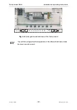
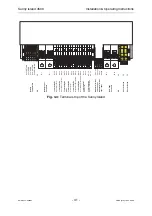
Table 3.1 shows the connector assignment on the terminal strip of the Sunny Island:
Designation Description
Comments
X1:1
+ RETURN
X1:2
+ SEND
X1:3
- SEND
X1:4
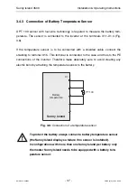
Battery tempera-
ture sensor
- RETURN
X1:5
Shielding
Possibility to connect shielding of sensor cable
PE
Chassis earth
Connection to ground, 2.5 mm²
F1: +
terminal block / 63 A fuse, 25 mm²
F1: -
Battery input
terminal block / 63 A fuse, 25 mm²
K1:14
K1:13
Relay K1 (Gen-
erator start)
Relay K1, special functions are described in detail in Table 8.5
K2:14
K2:13
Relay K2
(Generator con-
tactor)
Relay K2, special functions are described in detail in Table 8.5
K3:14
K3:13
Relay K3
(Mains contactor)
Relay K3, special functions are described in detail in Table 8.5
K4:14
K4:13
Relay K4
(SI contactor)
Relay K4, special functions are described in detail in Table 8.5
K5:14
K5:13
Relay K5
(Syncsw. / oper-
ate / load)
Relay K5, special functions are described in detail in Table 8.5
K6:14
K6:13
Relay K6
(Gen. crank / op-
erate / load)
Relay K6, special functions are described in detail in Table 8.5
K7:14
K7:13
Relay K7
(Battery fan)
Relay K7, special functions are described in detail in Table 8.5
K8:14
K8:13
Relay K8
(Battery circula-
tion)
Relay K8, special functions are described in detail in Table 8.5
X2:1 / -I
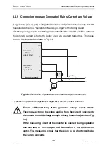
Generator/Mains current measurement input, via current probe, K
X2:2 / +I
Generator/Mains
current input
Generator/Mains current measurement input, via current probe, L
X2:3 / L
Generator/Mains voltage measurement input, L
X2:4 / N
Generator/Mains
sync. input
Generator/Mains voltage measurement input, N
F2:L
25 A fuse
F2:N
AC outlet
25 A fuse
PE
Chassis earth
Connection to ground 2.5 mm²
PE
Chassis earth
Connection to ground 10 mm²
PE
Chassis earth
Connection to ground 10 mm²
Table 3.1:
Description of terminal strip

