background image

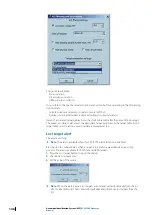
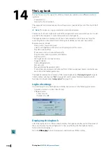
Loading a logbook

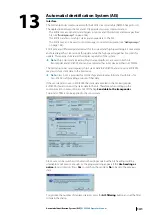
Click the Load button to open the Log files dialog. The current logbook is closed every day at
24:00 hours and stored in the logbook database. A logbook is defined by a name, which is by
default the date, and can be loaded from the database to be displayed and replayed.

The loaded logbook will be shown in the logbook window, replacing the current logbook.
When unloaded, the current logbook is re-displayed in the window.

Backup a logbook

Select the logbook name, push the button 

Backup

 and select the folder in which the

logbook will be stored.

Replay

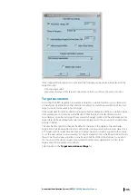
This function allows replaying exactly the main events which occurred during the navigation,
in particular ECDIS loads and scales automatically the charts as they were and triggers and
acknowledges alarms as it has been done during the voyage.

To initiate replay click on the 

Replay

 button in the 

Log

 window.

 Warning: 

The replay function must be used carefully, preferably only

when the ship is in harbor. During replay all navigation functions are
deactivated, the ship is no longer monitored and the logbook recording is
suspended.

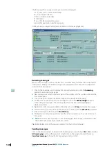
The Log replay window allows the user to control the replay.

Start replay

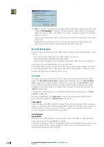
To start the replay click on the Start Replay button.

By default, the start time for replay is the time of the first logbook entry.

To suspend replay click the Suspend button

Ú

Note: 

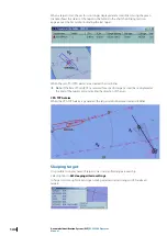
During replay most of the navigation functions are available, however the route

planning and monitoring functions are not enabled. During the replay the chart is
automatically loaded, scaled, and scrolled, and the logbook window scrolls automatically
to display the replayed data.

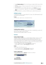
Adjusting the replay starting time

Three different methods are available:

Use of the Backward and Forward buttons for scrolling the logbook adjusting the start
time.

One click of a button will adjust the time by one Jump step.

Click in the text box time, select the appropriate field, and enter the desired value .

154

The Log book 

| ECDIS900 Operator Manual

Содержание Maris ECDIS900

Страница 1: ...ENGLISH MarisECDIS900System Operator Manual http www navico commercial com ...

Страница 2: ......

Страница 3: ... Copyright Copyright 2017 Navico Holding AS Warranty The warranty card is supplied as a separate document In case of any queries refer to the brand website of your display or system www navico com commercial Regulatory statements This equipment is intended for use in international waters as well as coastal sea areas administered by countries of the E U and E E A This system complies with CE under ...

Страница 4: ...on describes new features and enhancements in relation to reliability robustness performance and usability of the ECDIS900 New features and enhancements Description Reference CMAP Chart database An IEC 61174 Ed 4 approved chart module for SENC distribution which handles new requirements for Viewing group management Chart handling Review update Manual update For installation and update see C MAPcha...

Страница 5: ...e 19 The main window 19 Window title 20 Toolbar panel 21 Chart area 21 Console area 26 Security and system settings 27 ECDIS settings option 30 Tools for safe navigation 30 Man over board MOB 30 Adding an event 31 Selecting chart area 33 Center on ship 33 Auto centering 34 Targets 35 Loading Unloading objects 35 Ship to point range and bearing 35 Point to point range and bearing 36 Ship to anchori...

Страница 6: ...information 120 Selecting waypoints 122 Waypoint properties 122 Plotting a waypoint outside the screen 122 Rename waypoints 123 Delete a waypoint 123 Move a waypoint in the list 123 Waypoint ETA information 123 Fixed ETA function 124 Waypoint arrival warnings and alarms 125 Change active waypoint 125 New waypoint by coordinates 125 New waypoint by bearing 126 Set a new waypoint latitude longitude ...

Страница 7: ...ges 149 AIS data server 149 SeaTrac 152 The Log book 152 Logbook settings 152 Displaying the logbook 153 New log entry 154 Loading a logbook 154 Replay 155 Print 155 New logbook record 156 Capture screen client 157 Master bridge assistant MBA 158 NAVTEX 158 Graphical display 159 Access to Navtex message 160 Editors overview 160 General tools 160 Selection 161 Edit menu 162 Navigation Editor 168 Ob...

Страница 8: ...ule configuration 198 Annexes 198 Terms and abbreviations 200 Profile configuration parameters 202 Troubleshooting 202 Encryption scheme errors in ENC 203 Common errors in ARCS chart management 205 Maintenance 205 Weekly 205 Monthly 8 Contents ECDIS900 Operator Manual ...

Страница 9: ...al certificates are available from the product site on www navico com commercial The operational area of this ECDIS using ENC charts is between latitude 85 N and 85 S The International Hydrographic Organization IHO standards the system should meet are available at www iho int ECDIS requirement According to the SOLAS convention three key components must be fulfilled if a vessel is to satisfy the ch...

Страница 10: ... information ECDIS900 is designed to work on Windows operating systems Ú Note Asterisk indicates components that are mandatory for the ECDIS900 system ECDIS900 can be connected to the Internet to utilize online chart update The system is connected by using a shielded Ethernet RJ45 cable Ú Note To fulfill the ECDIS requirements the system must be connected to internet through a firewall To setup th...

Страница 11: ...ity settings button Click once to display the security settings dialog See Securitysettings on page 12 for more details 2 Reboot the computer button Click once to restart the computer 3 Switch off the computer button Click once to turn off the computer 4 ECDIS900 button Click once to open the running ECDIS Ú Note Users running in Operation Mode cannot terminate the ECDIS application unless the com...

Страница 12: ...s running in Service mode or Operation mode Ú Note It is mandatory to input the old password before you can completely change the password 3 Operation Mode button Click this button to enable Operation mode This is the default mode of the ECDIS system after the installation process See Operationmode on page 17 for more information 4 Service Mode button Click this button to switch to Service mode Th...

Страница 13: ...ogy that allows a human finger including several types of gloves to control the unit ECDIS MK5 computer MK5 computer is an Intel quad core Central Processing Unit CPU with HD graphics This standard CPU has a DVD drive 2 display port connectors 1 serial port VGA 2 USB ports 1 USB LAN port and 4 RJ45 LAN ports MK5 monitors The ECDIS900 MK5 system includes various display sizes The monitors are non t...

Страница 14: ...hernet bridge networks and standard NMEA 0183 IEC 61162 1 2 interfaces NMEA 0183 4 port expansion module It is a USB type interfacing device which is used to connect equipment such as GPS gyro log ARPA wind echo sounder etc This is normally designed to be connected at the back of the ECDIS computer unit This device is optional and is sold separately 14 System components ECDIS900 Operator Manual ...
Страница 15: ...perator manual of your monitor for more details Adjusting display brightness Warning The use of brightness control may inhibit visibility of information particularly when using the night colour tables Adjust the night display of the display screen by contrast control and not by brightness control Brilliance For MK15 the display brilliance is adjusted by touching the illuminated plus and minus symb...

Страница 16: ...etwork is predefined as Monitoring Station and acquires Position Gyro and Log data via serial lines A secondary Position Gyro and other sensor data inputs through the Planning Station All serial sensor inputs are broadcast on the network and shared by the two ECDIS stations Switching display to Korean language To change the display language of the ECDIS system to Korean language double right click...

Страница 17: ...nt to use You can also press F9 key from the keyboard to select another type of chart database Pressing the F9 key will only select chart database that are configured in the quick switch option Quick switch To display and configure quick switch between chart types press CTRL key and F9 key simultaneously Check uncheck the chart type and click the OK button to apply the changes Ú Note Only installe...

Страница 18: ...n out function should only be used for short periods of time Print screen Print screen allows you to screenshot screen capture or take a picture of the entire ECDIS screen To print screen click on the Print icon from the toolbar panel The system will automatically generate a screen image and convert it into pdf format You can save the image into a removable drive or in the local drive of the ECDIS...

Страница 19: ...isplayed Example S57 HO ENC RCDS or CMAP When S57 ENC or C MAP chart is active the following information will be shown in the title bar Type of layer display Currently used datum Type of projection Type of ECDIS workstation When raster chart is active the following information will be shown in the title bar Name of the active chart Chart number Datum of the chart Datum shift with WGS84 Type of ECD...

Страница 20: ...ntering icon Left click Show Hide Tide stations and ocean current Right click Tide stations Centre on Ship icon Weather handling icon Left click Ship properties Left click Show ports Right click Ship profiles Right click Port list Left click Conning to point range and bearing Options icon Right click Bow to point range and bearing Point to point range and bearing icon Print icon Left click New rou...

Страница 21: ... overscaled or not Refer to Scaleindicator on page 22 for more details The wind indicator displays the alphanumeric values of the wind True or Relative The depth indicator displays either the depth under the keel the Transducer or the surface according to user s selection Refer to Otherpanels on page 23 for more details The alarm panel displays alarms and warnings and includes the alarm acknowledg...

Страница 22: ...art in use Navigation mode panel GPS mode The GPS or D R Dead Reckoning panel displays the current navigation mode The default standard mode is the GPS mode The GPS name and data quality bar are displayed on the panel If no data is received the system switches to the D R mode and the NO POSITION warning message is displayed Once the communication with the GPS is restored the system reverts to the ...

Страница 23: ...rtdepths on page 60 Wind panel The wind panel displays either True or Relative values of the wind Right click on the panel and select the setting Select Show wind indicator from the menu to display the wind indicator in the chart area Drag and drop to set the proper location in the chart area Ú Note The indicator is transparent Depth panel The depth panel displays either the depth below transducer...

Страница 24: ... A11 Chart of 5m accuracy with sea floor coverage A21 Chart of 20m accuracy with sea floor coverage B01 Chart of 50m accuracy from standard survey C01 Low accuracy or incomplete chart D01 Unreliable chart U01 Chart with quality not assessed Indications warnings The warnings can be indicated with highlighted texts and icons that are displayed in the Legend panel Warnings can be as follows An Oversc...

Страница 25: ... the ship position The following icons are displayed in the event a setting is reconfigured Icon Description CPA TCPA monitoring is OFF Standard display is customized Danger monitoring is OFF Danger display is OFF Chart date is different from the current system date The user interface ECDIS900 Operator Manual 25 ...
Страница 26: ...deep contour Console options To unlock and modify the ECDIS settings enter the correct password and click OK 3 Lock Sensor Monitor settings button Click to lock unlock the Sensor monitor settings When the Sensor monitor settings are locked users cannot add new sensors and modify the settings To unlock the Sensor monitor settings enter the correct password and click OK 4 Close button Click to close...

Страница 27: ...ype of work For example a configuration can be defined for route monitoring displaying only active waypoint drift and target information Another configuration can also be defined for docking including Ship s parameters drift and the cursor position Ú Note The settings are password protected To unlock refer to Securityandsystemsettings on page 26 Creating a configuration The Default and Approval co...

Страница 28: ...ck off the Use PC time checkbox to manually set the UTC date and time Tick on the Use PC time checkbox to use the PC date and time Ú Note The time zone is by default displayed with the plus sign in Western hemisphere and the minus sign for the Eastern hemisphere The Chart time area contains time and date parameters for the charts By default the parameters are synchronized with the ECDIS time When ...

Страница 29: ...iles You can save custom ECDIS parameters configuration as a specified profile One the configuration has been defined set the profile name and click the Create profile button To use one of the saved profiles select the profile from the drop down list and click the Restore profile button Refer to Profileconfigurationparameters on page 200 for list of parameters Security and system settings ECDIS900...

Страница 30: ...aypoint A new log entry is stored in the logbook with the MOB position and navigation parameters Ú Note To delete an MOB select the MOB waypoint right click and select Delete on the pop up menu To view and manage the properties of a waypoint right click the selected waypoint and click Properties from the pop up menu Ú Note AIS SRM message is sent after confirmation Adding an event To plot a new po...

Страница 31: ...edefined scale of your chart area click the Select area icon from the toolbar panel A chart area is defined by Name LAT latitude LON longitude Scale Creating new display area To create or record the current position of the chart area click the New display area button and input the desired name of the newly added chart area Tools for safe navigation ECDIS900 Operator Manual 31 ...

Страница 32: ...art name is automatically created with the geographical center and scale 4 Change the auto populated chart name to desired chart name 5 Close the window Creating new area by keyboard To set a new chart area using keyboard follow the steps below 1 Click the New area by keyboard button once to display the Display area parameters dialog 2 Enter the name the latitude and longitude of the point center ...

Страница 33: ...large as possible in front of the ship This zone is defined by default as a rectangle located in the middle of the screen Dynamic centering zone Using a dynamic centering zone guaranties that you always have the largest chart displayed in front of the ship even when the heading changes After the zone is defined ECDIS900 dynamically sets the centering zone according to the heading For example if th...

Страница 34: ...d hide targets Relative vector Click the Draw relative vector button to display the targets with relative vector A relative vector is displayed in dotted line to distinguish from an absolute vector True vectors are displayed in solid lines Press the V key to switch between True vector to Relative vector AIS message start and stop AIS server The system allows sending and receiving short messages to...

Страница 35: ...played and measured from the conning position defined in ship parameter 2 Move the cursor to the desired position range and bearing and click to fix the point Ú Note Use the object menu for removing a single VRM EBL To remove all VRM EBL use the Delete key from the keyboard or the Clean chart function from the chart menu Point to point range and bearing 1 To set two points at a fixed range and bea...

Страница 36: ... point and the ETA 2 The position of the VRM EBL popup window is user adjustable Left click and drag to reposition the prompt window Modifying the ship properties Click the Ship properties icon from the toolbar to display the Ship properties dialog This enables users to manage vessel information settings and parameters Updating the vessel information To modify the ship name type and size follow th...

Страница 37: ...ds HS Hazardous Substances MP Marine Pollutants There are four 4 levels of hazard Level 1 Major hazard A Level 2 Hazard B Level 3 Minor hazard C Level 4 Recognizable hazard D When Manual entry option is not selected the Destination and ETA are automatically filled in when a route is activated The destination is the destination entered in the Route properties and the ETA is continuously updated by ...

Страница 38: ... mode When the D R mode is active the Ship Position values can be adjusted at any time on top of the page Simulation mode The Simulation checkbox must be ticked on before heading and speed can be changed Adjust the heading STW drift speed and the direction by entering new values using the keyboard or by clicking the arrow up down The values added are used to calculate the COG and SOG Ú Note In sim...

Страница 39: ...enerate a huge track file containing lots of points that are time consuming to display The above example is the recommended value to avoid creating huge files and without losing important ship track information Saving tracks To save a selected track right click on the track and select the Properties item from the list Select the Save tab and enter the desired track name date and time Click the Sav...

Страница 40: ...ent track must first be disabled from track recording before it can be unloaded Modifying track properties To modify the track properties right click the track and select Properties from the list A dialog similar below is displayed Modify the track name including the date and time the track was recorded and the number of points recorded along the track Duration is a time used to sail the length of...

Страница 41: ...rations are available for editing on the Monitoring station only Guard zone Tick on off the Check safety zone and anchorage zone to activate deactivate this function A safety zone can be set in front of the ship for automatic monitoring inside the defined zone and the vessel s crossing The zone is defined as a cone by an angle and a distance Set values for angle and distance to define the cone sha...

Страница 42: ...er alarms CPA Closest point of approach TCPA Time to closest time of approach XTD Cross Track Distance TCS course changing style To enter the alarm criteria e g XTD limits the waypoint arrival limit the first and second alarm time refer to Routeoptions on page 111 Display tab Color settings You can define colors of the ship symbol and shape plot 1 To set the color click the Day color button The co...

Страница 43: ...the Scaled icon check box to display the ship icon with its right scale 2 To display a line to the active waypoint tick on the proper check box 3 Set the desired Vector time value The length of both the ship s vector and the target s vector depends on the ship s speed and the vector time value 4 Tick on Display to display Range circle s around the ship Set values for Number of circles Range circle...

Страница 44: ...nates will change Click Default to set values to the default values Click Scale to reset the scale of the window to enable the ship to fit inside GPS antenna The GPS antenna is displayed as a circle with a cross inside it There are two ways to change the antenna position Double click on the antenna s name in the list The position settings dialog appears Set the position and click OK Click on the a...

Страница 45: ... the ship at her correct scale Ú Note This operation is available in the Monitoring station mode only Radar antennas Both the Radar antennas are displayed as a white square There positions are changed the same way as the GPS antenna s one The radar position affects the radar overlay display To select the active antenna use the Radar tabe on the console See Radar on page 127 Conning position The co...

Страница 46: ...on the port icon to access to all information stored in Fairplay database Tide and current information Click the button Show Hide tide stations and ocean current and icons showing the tide level are displayed at the tide stations locations There are more than 2000 main tide stations are available in ECDIS900 Ú Note The icons are visible when the chart scale is bigger than 1 2 000 000 Select the ti...

Страница 47: ...al predictions are calculated from a set of harmonic constants Secondary ports same as Standard port however the observations made to collect this information generally were not as extensive as with standard ports and so the tidal predictions are of average quality Secondary ports non harmonic These ports do not have any harmonic constants instead their tidal predictions are calculated by taking t...

Страница 48: ... following file formats are supported grib grib2 for waves current temperature wind force and direction pressure swell etc additional data typhoon ice proprietary formats of providers Ú Note Local area forecasts are 5 7 days only The 9 days forecasts are for ocean areas Ú Note NAVICO disclaims responsibility for grib grib2 files supplied by the providers which are not in the recommended list if th...

Страница 49: ... to set the current date and hour Ú Note In case of historical data the slider jumps to the end of the period 7 Layers button Click to enable and display the layers 8 Settings button Click to display the Settings dialog Weather files management dialog All weather files are stored in the subfolder called Weather in the folder ECDIS_Userdata and are automatically listed in the file management window...

Страница 50: ...llowing layers can be available current temperature pressure visibility waves ice wind typhoon swell Use the settings dialog to define colors and other layer parameters 50 Tools for safe navigation ECDIS900 Operator Manual ...

Страница 51: ...info Ú Note No more than one layer can be filled in Some layers have the direction parameter unavailable Example The wind display with all parameters switched on looks like that Ú Note To see the entire text information put the cursor on the selected location and wait about several seconds The tip with information appears Tools for safe navigation ECDIS900 Operator Manual 51 ...

Страница 52: ...NYK Guard Zone settings The NYK group has established an NYK standards values for safer navigation using ECDIS 52 Tools for safe navigation ECDIS900 Operator Manual ...
Страница 53: ... ship name or select the ship name and click the Load button 2 Left click the Ship properties button to display the Ship properties dialog 3 Modify the parameters accordingly Updating own ship data It is possible to update the ship data in the ship library based on the own ship data received from the pilot plug of the AIS transponder When receiving own ship data for the first time after connecting...

Страница 54: ...opean countries Japan HO for Japanese areas MPA for Singapore harbor etc NAVICO chart service includes several services to help the user including Delivering charts from different sources Information on ENC availability Quotation and ordering facilities for specific areas or for charts along ship s routes Handling and sending updates from several sources ENC data from one source are delivered on 2...

Страница 55: ... 2 V3 4 and IEC publication 61174 Annex E When a symbol is picked the broken square sign indicate its state Course up display mode ENC may be displayed in two different modes Course up or North up To select the display mode right click on the chart and check on or off the item menu Course up North up symbol is shown in the top left corner of the chart area Cells borders The cell boundaries are dis...

Страница 56: ...the chart and the chart will be centered in that position Another way is to press the mouse wheel and drag the chart Use arrow keys to scroll the chart to north east south or west Click inside the chart area to set focus then use the keys Other manual scrolling Use the Center on ship function to center the chart on the ship See Centeronship on page 33 for details Localization on the route Select a...

Страница 57: ...r will load automatically the chart with the most precise scale Distance measuring To measure the distance from one point to another point located outside of the chart move the cursor in the required direction outside of the chart area left clicking on the black screen area outside of the chart border will load automatically the chart with the most precise scale Waypoint move To move a waypoint ou...

Страница 58: ...hip To activate the Follow the ship mode right click anywhere on the chart and select the menu item Follow the ship Operating in the Follow ship mode the ECDIS900 automatically moves the current chart or loads new cells according to the ship s movements Auto loading mode When the Auto loading mode is ON ECDIS900 automatically loads new and displays the chart with the best scale at the ship s curre...

Страница 59: ...n one month or the chart is not installed and the permit will be expired in less than one month Chart settings When a ENC chart is first displayed the cell is displayed at the largest scale available in the SENC for the displayed area and the standard display provided When several cells appear on the display the boundaries between cells are displayed Ú Note It is not possible to remove information...

Страница 60: ...es and traffic separation schemes It is not possible to toggle off the Display base item The All configuration contains the maximum of layers to display including depth spots cables and pipelines ferry crossing names depth contours deeper than the safety contour Presentation settings With the Simplified presentation symbols are displayed in a synthetic way In Paper like presentation the presentati...

Страница 61: ...onsidered to be safe for the ship This is very important when the ship is approaching isolated dangers On the chart the soundings with a depth value lower than the Safety depth are displayed in dark grey but the soundings with a depth value bigger are displayed in light grey color Both soundings can be displayed or hidden by checking on or off the check boxes Deep Soundings and Shallow Soundings i...

Страница 62: ...mber of displayed soundings is too big making unreadable the figures on the chart Filter sounding function reduces the number of soundings in such a way that in case of ambiguity the shallower sounding is always used Cells loading mode The Automatic mode is default mode When Automatic mode is activated ECDIS900 scans all ENC database to load and display the proper cells for the scale in use When U...

Страница 63: ...pact to display all information at any chart scale Examples Three charts are displayed with different values of depth and deep contour settings The initial settings The deep contour value is changed Charts ECDIS900 Operator Manual 63 ...
Страница 64: ...ects present under the clicked point highlights these objects on the chart and displays information concerning them and the cell the objects belong to Ú Note The properties of other points on the chart can be viewed without closing the properties window by clicking on selected points Cell The Cell tab displays general information about that cell where the cursor is located In particular cell bound...

Страница 65: ...e Navigation tab displays information about Navigation aids lights beacons buoys etc If notes or pictures are associated with the selected cell they are available in the appropriate drop down lists To open a note or a picture select it from the list By default objects of the category C are not displayed in the list Click the Cat C button to make them visible Also you can open these files without o...

Страница 66: ... the list Click the Cat C button to make them visible To copy the entire list click the Copy button Light sector lines The Light lines tab displays light sector lines for a selected light You can expand several or all sectors and set the range value It helps to control very precisely the navigation when sailing towards the light or within selected chart sectors Ú Note These lines are displayed on ...

Страница 67: ... updates for the cell or cells if there are more than one cell is under the cursor Legend The tab contains information for any point of the chart display The Legend panel in the Console area displays information for the ship position only See Legendpanel on page 24 Chart handling Click the Chart handling button to open the Chart handling dialog Ú Note The chart management is available from this di...

Страница 68: ... 7 Update buttons Display updates opens the Display updates dialog for the current collection History of updates opens the History of updates report for the current collection 8 Reports and testing Set Test Mode switches the system to the test mode ENC Status Report opens the report for the current collection ENC security The ENC protection is compliant with the S 63 standard Security frame give a...

Страница 69: ...s file is sent on board This file contains the complete list of permits purchased by the user and must be installed as described above The new permits are added to the old ones Permits and chart version When a chart is reissued Old version is replaced by a newest one stored in general on the chart update CD a new permits file is sent on board This file contains the complete list of permits purchas...

Страница 70: ...ption allows the user to make a selection of charts to be installed and the source of the data CD or HD Make a selection of charts in the second dialog and click the Next button to start with the installation For more details refer to Chartselection on page 71 Ú Note European ENC charts and updates that are distributed by Primar and UKHO are delivered as Base CD which contains the chart database i...

Страница 71: ...n page 70 for details Ú Note If a large number of charts are involved the process may take some considerable time The function See Updates allows checking the last updated objects and the function Update history maintains a log of all applied updates see Updatehistory on page 74 When Cancellation update is applied the cell is removed from the collection Errors while update is in progress If the up...

Страница 72: ...e discarded ECDIS rejects an update related to a new edition of the cell ECDIS rejects an update related to an older edition to the cell Display updates Updates are displayed for a selected chart collection when the Display updates function is called from the Chart handling dialog see Charthandling on page 67 for a selected chart area for charts under a selected route Display chart updates inside ...

Страница 73: ...ld cells edition are marked with red circles Current cell editions are marked with green circles The update names are identified as follows Green circle in front of the update shows that the update review is available Red icon is used when update are not available To expand the session list and view the session update select the name of the modified object and click the Highlight selected object b...

Страница 74: ...updated cells under the route Update history Update history of a collection To display the update history of entire collection click the History of updates button in the Chart handling dialog An individual cell update history is available in the ENC properties dialog Display the update history with information about when the updates have been applied and which cells were updated Cancellation updat...

Страница 75: ...on is displayed while the chart status is changed or the chart is moved from the displayed chart area NON ENC Data available Refer to paper chart Manual cells loading is activated Some installed cells are not displayed due to invalid or absent cell permit Permits of some ENC cells are expired These cells may be out of date and MUST NOT be used for Primary NAVIGATION SSE27 Some ENC is not up to dat...

Страница 76: ... Click the Print button in the report window Charts under the route status report This report is for licensed charts of PM and GB collections only 1 Right click on the route 2 Select Chart status report from the menu 3 Click the Print button in the Report window AIO Layer A specific Information Layer AIO Admiralty Information Overlay is available in areas covered by ENC cells present in AVCS colle...

Страница 77: ... Update request and response The online update is possible when the PC is connected to Internet This can be done in different ways The ECDIS PC is connected to the LAN and a PC on the LAN is the Internet access server with the MBA software installed Charts ECDIS900 Operator Manual 77 ...
Страница 78: ...ternet to the chart server Response After few minutes a user receives an answer ECDIS900 detects automatically answer from the chart server and applies the update to the database after informing a user C MAP charts C MAP charts are ENCs that are compatible with ECDIS900 version C MAP offers not only ECDIS approved ENCs but also enhanced global coverage of digital charts C MAP charts are copyright ...

Страница 79: ...f the ECDIS software If C MAP was not included it is mandatory to uninstall and remove all ECDIS components and reinstall to ensure that the C MAP runtime is selected and included in the installation Refer to Maris ECDIS900 Installation Manual for more details 5 Click the Install new database button 6 Select the file called C93_ROOT from the DVD disc Ú Note The version or issue number of the datab...

Страница 80: ...ken device with a unique eToken key An eToken key is a short number used to identify the system which is written on a small tag attached to the eToken USB device A license made for a particular eToken will work only in combination with the particular key which it is made for Ú Note It is mandatory that the eToken USB device should not be removed from the ECDIS computer before or after the installa...

Страница 81: ...tion to your Internet provider 2 Click the Get update from Internet button in the Chart handling dialog 3 Then the procedure is automatic and several messages displayed in the Messages area of the dialog give information about the process The Copy database function allows a user to update other ECDIS station by LAN after Update is completed See Copydatabase on page 82 for more details Update via e...

Страница 82: ...cludes Zone or area ID Permits Expiry date for the permits To renew the chart permits before expiry date send to NAVICO an order for license renewal A renewal code will be sent back and entered using the button Renew All Licenses Copy database Copy database function is used to install the new updates in other ECDIS devices It is used to synchronize a remote ECDIS by LAN 1 Select accessible path an...

Страница 83: ...way than official ENC data with very little difference For more information about vector chart in ECDIS refer to the chapter S 57 charts Chart settings Select S52 view to display the vector char using official Presentation Library or C MAP view to display with C MAP presentation History of updates Click the History of updates button to get all information regarding the updates applied to the datab...

Страница 84: ...rovided using the same ARCS license The chart licenses and updates have to be installed and updated locally on each workstation Using ARCS charts In this chapter the user will learn how to Access to the Chart handling dialog see Charthandling on page 85 to get all information about the chart database to install delete or update charts Install chart permits see Permits on page 86 Install new charts...

Страница 85: ...rt handling The ECDIS900 software is copy protected with a dongle and Personal Identification Number PIN Each ARCS chart permit has a unique 40 digit code linked to a UKHO User Permit Number issued against a customer PIN The PIN number must be entered when asked on the first occasion ARCS charts are installed The ARCS User License Number 6 digits is required when ordering charts Entering PIN code ...

Страница 86: ...ire a fully up to date chart outfit The user will be licensed to a specified chart holding for a defined period of time Within this period the user will be entitled to freely access all Notice to Mariners and New Editions that relate to the licensed chart holding At the end of the licensed period the user will have to renew the license or will no longer be able to access any of the charts Install ...

Страница 87: ... LAN 4 The charts with a valid installed permit are displayed with a green spot in the left hand column If the permit is not valid the spot is red Select the chart or charts to be installed and then click the button Install charts The charts are copied onto the hard disk 5 The list of charts can be sorted either ascending or descending by each parameter By default charts with a valid permit are di...

Страница 88: ...with New Edition charts and Notice to Mariners corrections each week 1 Insert the update CD ROM in the CD reader and click the Apply update button The system will automatically update the charts that have a valid permit Ú Note If there are new edition charts on the update CD for which the user has valid permits then ECDIS offers to install the charts Ú Note Information regarding the update process...

Страница 89: ...place or used to augment the relevant NM chart correction by showing the user how the correction should be applied by hand 1 Click the Print Chart Updates bunnon to print the paper copy of the chart updated tiles 2 Select the tiles to be printed All tiles that have been updated since the base chart was issued The tiles have been updated only in the latest update procedure Checking the updated obje...

Страница 90: ... list Right click on the chart select Other charts and then select ARCS ECDIS lists all ARCS charts which are available at the current cursor position The color of the chart indicator display the chart permit status Green the chart permit is valid Yellow permit warning The chart permit must be updated 90 Charts ECDIS900 Operator Manual ...
Страница 91: ...er to load the ARCS chart directly from the Chart handling dialog Zooming ARCS charts are produced in their original scale such as 1 50 000 The ECDIS900 will always open a chart at its surveyed scale Original scale The user can zoom out to show half the chart area on the screen medium scale and out again to show the whole chart in overview low resolution The user can also zoom in to display the ch...

Страница 92: ...rt is loaded and displayed In seamless mode double click on the inactive chart to make it active By hot keys or buttons Press or to load the chart containing the center of the screen with higher or lower scale Alternatively right click on the zoom in zoom out buttons to achieve the same Chart settings To change the color scheme select the relevant item in the color menu Toggle the box Display Char...

Страница 93: ...ific ARCS chart To access after update the list of T P still in force right click on the ARCS chart and select Properties Select the T P in the pop up menu located at the bottom of the window and a text window displays the text of the NtM Tip For each chart the list includes the specific notices that apply to the selected chart only plus all general T P Notices The Technical page displays addition...

Страница 94: ...ith adjacent charts where possible as detailed below Only ONE chart active at a time the surrounding charts are shown in the same datum and at the same scale as active one but are shadowed Ú Note Whilst the surrounding charts are displayed at the same scale this may not be their natural scale The surrounding charts shown could be built from several different scale charts zoomed to the scale of the...

Страница 95: ...that for the area of the screen not covered by ENC charts ARCS charts is used to complete the pictures Display strategy When ENC cells do not cover whole screen ECDIS900 looks for an ARCS chart with the closest scale within the limits of 4 times the current scale ARCS chart is then eventually shifted according to its datum and zoomed according to the scale in use If no ARCS chart is found the gene...

Страница 96: ... underline that it has become an alarm object The width is one pixel and the area is not filled Where the alarmed object is a point this is surrounded by a red rectangle Monitoring user alarm When the ship s guard zone intercepts an alarmed object an alarm is triggered The alarm is displayed as long as the alarmed object remains inside the ships guard zone Ú Note The guard zone depends on time and...

Страница 97: ...lanned routes can be loaded edited and displayed at the same time but only one route can be activated and used to monitor the vessel s position The active route is displayed on the chart by as pecked red line Creating route using keyboard 1 Select the icon Route plan in the toolbar 2 Enter first waypoint position in the dialog box 3 Click the OK and New button and enter the second and subsequent w...

Страница 98: ...ist and can be unload download edited etc at any moment Displayed information 1 Click on the chart at the first turning point along the route A waypoint WP 002 is placed at this point 2 To set the information that should be displayed for the route right click the route and open the Display tab 3 Then tick on the necessary parameters to display 98 Routes ECDIS900 Operator Manual ...
Страница 99: ...me zone for a selected waypoint can be changed in the Waypoint properties dialog see Waypointproperties on page 122 Download from GPS A route can be downloaded from a GPS The downloading process is controlled in the Sensor monitor application and could be performed from the Sensor monitor as well as from the ECDIS route menu Different types of routes can be downloaded from the GPS A complete route...

Страница 100: ...outeplanoverview on page 102 Append a waypoint Locate the cursor on the last leg Right click and select Append new waypoint from the drop down menu A new waypoint will be appended to the end of the route Move the cursor to the desired position The new segment will display the appropriate length and heading To stop adding new waypoints double click on the last waypoint entered Delete a waypoint Loc...

Страница 101: ... up menu Ú Note When the function Undo is activated several times the modifications made to the selected route will be cancelled one by one Route properties For route properties locate the cursor on any leg of the route right click and select Properties from the pop up menu Alternatively move the mouse on top of the route and press F4 several times to access the route Properties dialog General tab...

Страница 102: ...ter a waypoint has been added to or deleted from the route The Information tab allows entering additional information about the route Information tab Link with OE file Create a file with Object editor tools including points line areas or text Link the file with the current route Loading a route When the route is loaded and activated the OE file linked with the route is automatically displayed When...

Страница 103: ... the Waypoint properties button to access editing dialog Clicking on a value in the list and edit this value in the dialog Clicking the column title of an editable value to change all values like the SOG turning radius XTD in the column at the same time Ú Note When the route is locked the buttons are disabled and fields cannot be edited Unlock the route to make the components editable Ú Note Modif...

Страница 104: ... value is entered in the Option dialog panel Route Ú Note Click in the title XTD to modify XTD for all legs Set SOG Use the same procedure as for Set new turning radius By default the SOG value is entered in the Route Properties dialog box Ú Note Click the title SOG to modify SOG for all legs Set ETA Click on the ETA value of the leg and enter a new ETA Then the leg SOG will be re calculated Ú Not...

Страница 105: ...ne 1 To modify the time zone to the selected waypoint click the Modify TZ button 2 Set the value and click the OK button to save Add a route 1 Click the Add route button 2 Select the route and click OK The selected route will be added to the current route Ú Note It is not possible to select multiple routes in this operation Routes ECDIS900 Operator Manual 105 ...
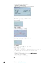
Страница 106: ...oute leg Distance from the leg in NM and time of creation are clearly displayed in the label of the line This line is part of navigational editor and therefore it is possible to edit the change the position and length at any time Parallel index is recorded in the logbook Load unload and delete route functions To load unload routes or tracks click on the Load Unload objects button in the toolbar Cl...

Страница 107: ...rt Use the Save as button to save the selected route into a different filename or location Use the Export button to download the selected route Use the Import button to load an existing route from a different folder location Use the Delete button to remove the selected route from the list Use the Localize button to center the chart on the selected route You lock unlock the selected route by clicki...

Страница 108: ...to check the routes against dangers of the chart and against user defined objects when vector charts are in use When raster charts are used only user defined objects are being checked To activate the Check route function locate the cursor on a route leg right click and select Check route from the list The function checks the route against all charted dangers that may be present along the route leg...

Страница 109: ...ist The bottom frame contains results of the route geometry checking To change the Guard zone settings click the Settings button Adjust the settings in the Guard zone window as required In case the checking result contains one or more danger objects the Guard zone settings are displayed in the caption of the window and the objects are listed in the left frame An alarm is red highlighted and a warn...

Страница 110: ...he color to gray Clicking on an item makes the chart centered on the selected danger An intersection of danger with the route safety corridor is highlighted too Ú Note It is possible to approve the route without approving displayed dangers The warning message is displayed in this case Ú Note It is recommended to check all dangers and edit the route before approval Danger highlighting The system hi...

Страница 111: ...ns icon on the main toolbar and then select the Route tab Default type of legline Select either Great circle or Rhumbline Turning radius NM default value for route creation Speed kn default speed value for route creation Route alerts Cross Track error m Toggle up or down to set the appropriate value or input it via the keyboard Waypoint arrival distance NM Toggle up or down for the appropriate val...

Страница 112: ... formats XML format with route file extensions rtz ECDIS900 format with route file extensions rtx The can also import other route formats from the previous ECDIS900 version with route file extensions rtu and other manufacturers routes like Sperry MaxSea Transas and others Ú Note Routes are stored in ECDIS using WGS84 datum When a route is imported it is important to select the datum that has been ...

Страница 113: ...ernatively a route can be activated from the Route plan window with the button Activate route Ú Note When an OE file is linked with the route the file is automatically loaded and all alerts of the file activated Display Only one route can be active at any time An active route is displayed differently than other routes on the chart inasmuch as the segment path is drawn dotted and the active waypoin...

Страница 114: ...f limits see Alerts on page 114 Ú Note The Wheel over Point WOP is calculated according to the turning radius value entered by the navigator It is extremely important to enter this value during route planning To select an active waypoint manually right click on the chosen waypoint on the chart or select the waypoint in the route monitoring plan Alerts When the XTD or Waypoint arrival alerts are ac...

Страница 115: ...ue for each remaining legs Ú Note In the picture above planned speed values are used to calculate ETA Waypoint ETA The console panel WP ETA displays the ETA at the selected waypoint Select the appropriate waypoint number Toggle on Planned speed or Ship speed for the calculation of ETA Target linked to a route One AIS target can be linked to a route 1 Right click on the target to open AIS target me...

Страница 116: ... can be linked to the ships autopilot to automatically alter course at each waypoint The amount of helm ordered by the ECDIS900 will vary according to turning parameters set in the system The helm ordered and rate of turn value NEVER exceed the limits defined by the user To complete a prescribed turn at a waypoint it is essential for the turning radius to be set into the system accurately Ú Note P...

Страница 117: ...thetrack The parameter controls how fast the ship comes back to the track The yellow point displayed on the route is the point the ship tries to reach Bigger is the value faster the ship will try to get back on the route but more intensive will be the rudder usage when the ship is sailing along the track CTSspeedlimit It is the maximum of course change per second that the TCS can accept Is not use...

Страница 118: ...nitoringthreshold degr The parameter is used to monitor two GYRO values Alert is triggered in case the difference exceeds the specified threshold Positionmonitoringthreshold m The parameter is used to monitor two GPS positions Alert is triggered in case the difference exceeds the specified threshold XTD calculation while turning Select XTD from ROT curve when using new autopilot type which needs X...

Страница 119: ...lected as the start waypoint When route is finished double click to finish the route creating the first waypoint at the ship position 3 A new route is created name is suffixed by _BACK Right click to activate The new route is activated Routes ECDIS900 Operator Manual 119 ...
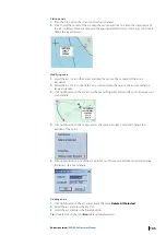
Страница 120: ... held down To de select a waypoint from a selection click the selected waypoint with the Ctrl key held down To add a complete route to a selection click on one waypoint of the route with the Ctrl and Shift keys held down Click once on a waypoint to select it With Shift key down click on another waypoint all waypoints of the located between the 2 clicks are selected Using together with Ctrl the sel...

Страница 121: ...several routes You can create a new route using waypoints of several routes 1 Load or create several routes 2 Select waypoints on the routes Hold Ctrl when selecting waypoints and Ctrl and Shift if you want to select entire route 3 Click the New route button from the toolbar 4 Confirm that you create the route 5 Enter the new route name and click OK The new route is ready with all waypoints select...

Страница 122: ...tting a waypoint outside the screen Scroll Scrolling the chart is achieved by moving the mouse outside of the chart area in the direction of the desired scroll or by pressing the arrows key on your keyboard Change scale At any time during the route creation process it is possible to zoom in or out or to change the scale of the chart by clicking right anywhere on the chart and selecting the desired...

Страница 123: ...ist 1 Right click on the waypoint s name and select the menu Move after 2 Then select the destination waypoint and the waypoint will be moved after the selected waypoint Waypoint ETA information The panel WP ETA displays the ETA value for any waypoint selected by the user The required waypoint is selected by clicking the small arrows on the RHS of the panel Select between Ship Speed and Planned sp...

Страница 124: ...wledgement 30 seconds before the WOP Course change Warning Ship starts turning onto the new course does not require acknowledgement WOP is reached Course change Alarm Require acknowledgement 30 seconds after the WOP is passed Back up navigator Alarm In case the Course change alarm was not acknowledged You can define other time both for the Early course change and for the Course change See Routeopt...

Страница 125: ...t possible to enter a new waypoint before the first waypoint with this method To add a new waypoint at the start proceed as follow Select the first waypoint Press the New waypoint by coordinates button and enter the name and coordinates for the new waypoint Right click on the first waypoint and select the menu Move after and select the number of the newly created waypoint Ú Note When a new waypoin...

Страница 126: ...on the longitude value in the list and input the proper longitude Set a waypoint as a Pilot waypoint To set waypoints of embarking disembarking a pilot right click on the waypoint name and select the proper item The waypoint name becomes red colored To cancel this waypoint property select the No pilot action item Center the chart display on the waypoint location Double click on a waypoint s name t...

Страница 127: ...be shown on the chart and by means of the built in radar tracker you will now have the most common ARPA functions available The system to be installed on one or two machines which may operate on a local network onboard the ship MARIS radar tracking system has a unique capacity of tracking simultaneously up to 300 targets making it capable of searching for and showing data much faster than any othe...

Страница 128: ...h of the target to the ship Course Course of the target Speed Speed of the target Manual target You can create manual targets and keep their dead reckoning These manual targets are managed the same way as normal targets acquired from the ARPA 1 To plot a manual target click on the Set target button on the toolbar 2 Place the cursor at the desired position and click Targets will be drawn to the sam...

Страница 129: ...s by serial line the targets from AIS when AIS is interfaced to ECDIS Center the chart and access properties Double click on the target name to center the chart on the target Right click on the target s name to access to target s properties Show and hide targets Press Hide target to hide the targets All targets are hidden except the target on CPA TCPA alarms which will always been displayed Relati...

Страница 130: ...tware components includes the following applications Extractor Tracker VarpPCI exe Sensor Monitor Sensor Monitor exe ETS Agent ETSAgent exe PCI Board Adjustment SetupETS exe Remote PCI Board Adjustment RemoteSetupETS exe Oscilloscope Oscilloscope exe MARIS ARPA 2000 ARPA2000 exe Ú Note MARIS PC Radar Kit provides the ability of combining Radar operations with the ECDIS and is fully approved to IEC...

Страница 131: ...djust the ship s position and compensate eventual gyro drifting Display settings To show the Radar picture on top of the chart click the Overlay menu The Radar picture does not hide any chart information and is displayed in a transparency mode According to the regulations the Radar picture is displayed between two chart layers and essential chart information land contours lights and buoys etc is d...

Страница 132: ...s without closing the dialog The stabilization mode and speed sources could be adjusted in case when not all ordinary sensors are available The recommended combination is GPS stabilization and Log speed source Target tracking MK PC Radar kit automatically tracks the radar targets but displays them only on request There are different ways to acquire targets Manually Click the Acquisition button and...

Страница 133: ...w the central point The zooming rate could be specified in ARPA Settings dialog in range 2 6 The zooming window could be dragged using the mouse and zoomed content will be updated after fixing the window on certain position for a while The radar video in zooming window is updated synchronously with the radar antenna rotation The zooming window disappears automatically if not moved in 15 seconds Al...

Страница 134: ...If ARPA 2000 shows proper navigational parameters but the radar overlay is not correctly arranged Activate the System dialog in the ARPA 2000 Refer to the ARPA 2000 user manual Click the or buttons until the Extractor parameters page is displayed Modify the Headup parameter to adjust the orientation of the radar overlay Ensure to check it in ECDIS after each modification Modify Sync Delay paramete...

Страница 135: ...ceeded The caution is marked with a yellow square This alert goes on and off while the indicated condition exists Acknowledgment is not required By default a sound signal accompanies an alert message that is not acknowledged and the pulse frequency of the flashing of the alert button is 1 Hz The following sound patterns are used Alarm 3 beeps each 10 seconds the alarm can be silenced once without ...

Страница 136: ...e PC this alert is acknowledged on all PCs with the exception of user defined alerts which are local on the PC List of alerts Alerts have two categories A The information is required for the decision support The A category alerts are generated by workstation All alerts of the A category require to be acknowledged Can be acknowledged on the ECDIS PC only B no additional information is required for ...

Страница 137: ...te planning across safety contour prohibited areas and hazards indication Permanent indication Off state of safety contour prohibited area and hazard indication in route monitoring Permanent indication Chart scale is not uniform over the displayed area Permanent indication Viewing date or date range does not include current date Permanent indication Chart orientation is not uniform over the displa...

Страница 138: ...ght click on the object outline plotted on the chart and click Set alarm in the pop up menu The object outline changes to red to underline that it has become an alarm object It has width of one pixel and no filling for area Where the alarmed object is a point this is surrounded by a red rectangle When the object triggers an alarm the display changes the lines are drawn in red 2 pixels width 138 Al...

Страница 139: ...sing the item menu Select all alarm objects in the menu Edit in the editor panel and press the Delete selected objects button Anchor watching The function controls the ship position relative to an anchor point To set the offset value open the F Distance dialog from the Shape tab of the Ship properties dialog See Shapetab on page 44 for details 1 Right click on the ship icon and select Anchor watch...

Страница 140: ...or Harbor mode To suppress alerts buzzer and external BAS when vessel is in the harbor berthing or whatever switch on Harbor mode Alerts are disabled and chart area is hidden by big panel indicating that ECDIS is OUT of navigation mode CTRL H short key is used to activate the function Press the button on the harbor panel and the system is back to the navigation mode 140 Alert management ECDIS900 O...

Страница 141: ...d either in AIS device either in ECDIS900 The AIS transponder sends regularly ship s static data to ECDIS900 and vice versa ECDIS900 may send ship s static data to the AIS device Ú Note Class A AIS is provided for SOLAS ships and provides full data Class B AIS is for non SOLAS craft providing a subset of that data If the user decides to use in ECDIS900 the static data entered in the AIS transponde...

Страница 142: ...get see ShowandhideAIStarget sname on page 147 and the past track see Showandhidepast track on page 147 can be displayed and the track can be saved see Savethetrack on page 147 on the hard disk All information about the selected target is displayed in the dialog Properties of AIS target Target list contains the list of targets currently being tracked see Targetlist on page 129 The prediction tool ...

Страница 143: ...hecked to be able to enter manually the voyage data see Modifyingthevoyageinformation on page 37 Ship and voyage data are automatically sent via the serial link to the AIS transponder AIS target display The AIS target symbol is a blue triangle with a speed vector dotted line and the COG vector continuous line The speed vector length depends on the speed of the target true vector or on both own shi...

Страница 144: ... is received for a specific target a small bar is displayed at the end of the target vector indicating the direction of the turn CPA TCPA alarm When the CPA TCPA alarm is generated the target symbol becomes red and it blinks Sleeping target It is possible to display name of targets only in a specified range around ship Select options in AIS sleeping criteria settings In Target console right click ...

Страница 145: ...activated AIS target symbol and the alphanumeric AIS target data shall be automatically selected and displayed with the provision of an alternative priority in below The user has the option to change the default condition to the display of tracked radar targets and shall be permitted to select either radar tracking or AIS alphanumeric data Once a TT target and AIS target have become associated hys...

Страница 146: ...table In the target table no association is used and data is displayed as it is Lost target alert This alert is warning Ú Note The alert is available when the CPA TCPA alarm function is enabled Press button to configure alert when a target is lost within a given Range around ship position This alert is available for both AIS and ARPA targets 1 Press the Lost target button to open the dialog 2 Chec...

Страница 147: ...sk right click on the target icon and select Save track from the pop up menu The track is recorded for 3 hours with 30 seconds time stamp The saved AIS tracks are stored in the same database as the own ship and saved ARPA tracks To load or unload procedure of recorded target tracks see Managingtrackrecordings on page 38 AIS target properties To view the properties of a target click right on the ta...

Страница 148: ...g 4 Double click on the message to acknowledge it or push the Acknowledge button to acknowledge all messages The messages that have not been acknowledged are displayed as bold 5 Right click on the message to delete it from the list or click Clear to delete all messages 6 Select how long you want to keep the messages in the log with the Save last parameter 7 Print all messages with the button Print...

Страница 149: ... few seconds AIS targets are displayed on the chart SeaTrac SeaTrac Tender Tracking The SeaTrac Tender Tracking System is a stand alone Radio Frequency Transmission System designed specifically for tracking watercraft as they operate around a Superyacht The SeaTrac System operates without the requirement for land based infrastructure SeaTrac transmissions are without cost and operate on either US ...

Страница 150: ...nic alert see example above for TenderD when no internal alarm is activated refer to SeaTrac targetdisplay on page 150 SeaTrac internal alarm Three types of alarms can be activated regarding distance from own ship to Target The box should be check to get given alarm and Distance threshold adjusted But in addition for Tender approach and Tender towing alarm should be activated target by target Righ...

Страница 151: ... Alarm if Range Distance Automatic Identification System AIS ECDIS900 Operator Manual 151 ...
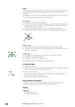
Страница 152: ...on and deletion Target positions AIS target position name and status Triggered alarms Acknowledged alarms Manual event Manual plotting Navigation Editor Position fixes are displayed in the tabular form Other navigational objects created by user are visible while replayng data only The logbook window lists all entries of the current logbook see Displayingthelogbook on page 152 and allows printing s...

Страница 153: ...he position of the ship the chart in use and the position offset is available To display the full text move the cursor onto the comment field and a small window will display the information Voyage record To display the voyage record press the button Load and select the file called using the following data format MM_DD_YYYYV4 lgf New log entry In case of a special event the operator can record the ...

Страница 154: ...eplay function must be used carefully preferably only when the ship is in harbor During replay all navigation functions are deactivated the ship is no longer monitored and the logbook recording is suspended The Log replay window allows the user to control the replay Start replay To start the replay click on the Start Replay button By default the start time for replay is the time of the first logbo...

Страница 155: ...ording function again Acceleration You can choose the acceleration rate for the display Adjust the rate with the Up and Down arrows The acceleration value of 5 provides replay of real time multiplied to 5 Print Click the Print log button on the Log dialog box and the Notepad will be displayed showing the content of the logbook Ú Note The Notepad application gives the user all possibilities to save...

Страница 156: ...Data Recorder Capture Screen Client supports UDP as TCP transmission For UDP transmission sending the image data using multicast protocol is also supported The requirements for UDP protocol protocol IP addresses ports are described in IEC 61162 450 edition 1 The demands to TCP protocol protocol IP addresses ports are described in IEC 62388 For more details refer to the Capture Screen Client User M...

Страница 157: ... based software which can be tailor made through the activation of different modules available to fit the mariner and ship owner needs and requirements ECDIS900 users with MBA can enjoy the benefit of automatic data synchronisation This integration gives even the most experienced navigator great advantages in management of chart handling and updates Ú Note Customers can obtain support by contactin...

Страница 158: ...renced message an icon or several linked icons are displayed on the ECDIS charts Click in the icon Navtex located in ECDIS900 Alarm panel to access to the Navtex window This window lists the messages which are currently displayed on the chart When the chart is scrolled or zoomed the content of the window may change The display of the messages on the chart is activated by the check box Display and ...

Страница 159: ...ly select the message and push Show message button From the chart right click on the icon and activate the menu Message status A message is either read either unread Closed envelop icon displayed in front of the message and bold characters shows unread messages The icon Navtex in ECDIS900 is either opened either closed Closed icon means that unread Navtex messages exist on the screen Opened icon m...

Страница 160: ...ection can be moved or deleted The tool Delete selected object delete the selection of NE or OE objects The tool Show Hide objects list displays the list of objects currently loaded Double click on the object to center the chart on the object Select the object and push the key Del to delete the object Selection A selection is a collection of selected objects of the same type NE or OE To make a sel...

Страница 161: ...ition Select Paste to Position the cursor changes and the selection will be pasted at the mouse click location This function is equivalent to the move selection action performed with the mouse Delete all selected Delete the Selection Select all object editor Empty the selection and select all OE loaded objects that do not belong to a locked layer Select all alarm objects Empty the selection and se...

Страница 162: ...sibility of storing these objects to file and reloading them in the system on request The different objects available are LOPFunction on page 162 Arcs on page 164 Points on page 166 CurrentInformation on page 166 Compass on page 166 Polylines on page 166 Parallelandperpendicularlines on page 167 Chartannotationandcaution on page 168 The Multi plotting mode allows plotting several objects without h...

Страница 163: ...earing point and drag the mouse as far as is necessary The time Stamp is saved and displayed 4 Select Line of position range NM for an arc Enter range in NM Enter LOP label displayed on the map 5 The cursor will change to a cross Move the cross on the point center of arc and Click on the position Object Modification Editors overview ECDIS900 Operator Manual 163 ...
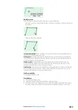
Страница 164: ...t a FIX position from LOP Here 1 line and 1 arc are used Option Set D R Create the Fix point and select D R mode at the same time Selecting a bearing line Either click left button on the line Either select the tool Selection with the left button of the mouse click on the chart and drag the mouse all NE objects included inside the rectangle are selected Deleting a bearing line Click right button on...

Страница 165: ... mouse the arc is modified in range and angle 3 Click right button on the arc access the menu Properties and modify position radius start or end angle 4 Click right button on the center access the menu Absolute Coord and change the position of the point 5 Click right button on one of the arc point access the menu Absolute Coord and change the radius start or end angle Deleting an arc 1 Click right...

Страница 166: ...he new location 2 Click right button on that point open the dialog Properties and modify position type of point time or log values Deleting a point 1 Click right button on the point and activate the menu Delete All Selected 2 Select the point and press the key Del 3 Select the point and press the Delete button Tip Double click on the tool Point deletes all displayed points Current information 1 Se...

Страница 167: ...ing right button on the point of the line and activating the item Delete point Other method select the line move the cursor on the desired point of the line and press the keyboard key D Split the line in two lines by selecting the line clicking right button on the point of the line and activating the item Cut point Other method select the line move the cursor on the desired point of the line and p...

Страница 168: ... displayed on the chart to enrich it The Object Editor OE allows plotting importing manipulating and saving user data Data are saved in files that can be loaded or unloaded on request Each files contains 8 different layers called by default Layer 0 1 2 3 4 5 6 7 and the user can select in which layer he wants data to be stored Each layer may be shown or hidden locked or unlocked and defined as vis...

Страница 169: ...he selected display attributes shown in the bar Choose different default display settings by clicking on the appropriate button Line type or width for the lines or icon type for the isolated point In the same way change the display characteristics of a selected object by choosing different display attributes after the object has been selected Control the display priority amidst the objects of a sa...

Страница 170: ...opy access to the file selection dialog press the load button and select the file to be loaded the selected file read from the hard disk will become the active file To make active a file that is already loaded in the system press the button Copy access to the file selection dialog and double click on the file s name Load Unload files To load a file push the button Load and select the file name in ...

Страница 171: ...elect a file or a directory name and press Unload The file or all files contained in the selected directory will be unloaded Save files When a file is modified it is not automatically saved on hard disk To save the modifications activate the file management dialog select the file and press the button Save or Save As to save the file with a different name Editors overview ECDIS900 Operator Manual 1...
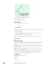
Страница 172: ...h order the layers are displayed the first layer of the list is displayed the first Each layer s name can be changed and the order the layers are displayed can be adjusted Moreover each layer can be made locked or unlocked shown or hidden and minimum maximum scales can be edited meaning that the layer is displayed only when the chart scale is comprised between these two scales User s data can be c...

Страница 173: ...t with the selected display attributes shown in the bar Choose different default display settings by clicking on the appropriate button Line type or width for the lines or icon type for the isolated point In the same way change the display characteristics of a selected object by choosing different display attributes after the object has been selected Control the display priority amidst the objects...

Страница 174: ...rawn in the order which they have been created But the display priority between two objects can be modified for example when a plain colored area plotted after an isolated point hides this point To make it visible select the area click right button on that area activate the menu Order and select the item To back To Back sends the object at the end of the object list of the layer while Back One mov...

Страница 175: ...escribed below can be cancelled with the item Undo from the menu Edit See paragraph Edit Menu Selecting objects A selection is a group of selected OE objects Select one object click on time on the object or on one of its edge Select two or more objects Selection containing several objects click on each object maintaining the keyboard key Ctrl down Activate the menu Select All OE objects from the m...

Страница 176: ... or an area Click right button on the line area at the desired location and activate the item Insert Point Another method Select the line area move the mouse at the desired location on the line area and press the keyboard key I Delete a point in a line or an area Click right button on the line area on the point and activate the item Delete Point Another method Select the line or the area move the ...

Страница 177: ... ECDIS the modification of objects is limited to adding text information or moving objects The latter is implemented as deleting the object and afterward inserting a copy The ECDIS provides functions to cancel or withdraw manual updates and to query objects which have been inserted by manual updates A manual update always has effect on only one particular cell This cell has to be assigned to the v...

Страница 178: ...nsert point objects 1 Click right button on the chart at the appropriate position and activate the menu Manual update 2 Select the object type point object 3 Select the type of point object you want to insert 4 Set the date values if it is necessary 5 Adjust by keyboard the coordinates of the point and press Insert 178 Editors overview ECDIS900 Operator Manual ...
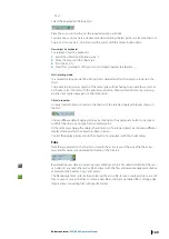
Страница 179: ...propriate position and activate the menu Manual update 2 Select the object type Line area objects 3 Select the type of line or area object you want to insert 4 Insert the list of coordinates of the line or area points or make the area by cursor 5 Set the date values if necessary 6 Press Insert Editors overview ECDIS900 Operator Manual 179 ...

Страница 180: ...ick OK Ú Note The object will appear in time Before the starting date it stays invisible but it is in the cell properties Move object Remove updates Move point objects 1 Click right button on the object 2 Activate the menu Manual update 3 Select the object type point object 4 Select one component of the object 5 Double click on the point coordinates and the new ones in the Select point position di...

Страница 181: ...omponents Edit area object The Manual updates dialog allows area objects modification 1 Right click on the area and activate the Manual updates dialog 2 Select the inserted object from the list and press Edit 3 Select a point to be moved 4 Move the selected point using mouse Move the selected point using keyboard Editors overview ECDIS900 Operator Manual 181 ...

Страница 182: ...d with the functions Delete all update available in the manual update window Ú Note The function is applicable only on the loaded cells Update history Press the button History to get the list of all manual updates applied on the cells 182 Editors overview ECDIS900 Operator Manual ...

Страница 183: ... from historical values and are used to predict ROT and heading The user has to enter proper ship s parameters and settings for a accurate calculation To run the function an interface to GPS and Gyro must be available Ú Note The heading input value should at least contain one decimal To activate the function press the button Target prediction and toggle the check box Use vector predictor ON The ac...

Страница 184: ...alculation includes the rate of turn Docking Ú Note The Docking mode available for speed lower than 6 kn To use the docking mode do the following 1 Click the Target prediction button 184 Predictor ECDIS900 Operator Manual ...

Страница 185: ...position For each anchoring point course distance and speed cm s are displayed 2 speed vectors are displayed from bow and stern Settings The following user defined settings are used during the calculation Maximum ship speed limit used in the calculation Maximum turn rate limit used in turn rate calculation Prediction duration ship symbol plot interval Time to reach ROT sets limit to turn rate acce...

Страница 186: ...e interval within the limit of ROT and time to reach the ROT Active leg window This option is designed to help mariners during navigation in narrow waters where precise following along the planned route is essential The ship s shape is displayed in the middle of the window together with the active leg and turning curves using a scale from 3500 10000 depending on the ship s dimensions The picture i...

Страница 187: ...tes a turn till time the ship actually starts to turn Those values can be adjusted in the dialog Distance to start turn To access the settings push the button Turning in ship properties page shape If ship is for some reason away from the active route the decision to start turn should be done using the criteria of crossing the line passing through WOP and parallel to next route leg Predictor ECDIS9...

Страница 188: ...cess to the SAR module Right click the New Route button from the toolbar panel A dialog similar below will be displayed Click Create the route button and modify the parameters SAR symbols According to IEC62288ed 2 SAR module displays AIS aids to navigation AToN symbols for physical and virtual objects Basic shapes Basic shape physical Basic shape virtual Purpose symbols 20 188 SAR module overview ...

Страница 189: ... for the virtual AToNs are represented in the same way with the virtual basic shape shown above Racon Emergency wreck mark North cardinal mark East cardinal mark South cardinal mark West cardinal mark Port hand mark Starboard hand mark SAR module overview ECDIS900 Operator Manual 189 ...

Страница 190: ...Isolated danger Safe water Special mark Failure symbols Off position Lights failure Racon failure Missing SAR aircraft SAR vessel 190 SAR module overview ECDIS900 Operator Manual ...

Страница 191: ...se Radius of search 5 Select the space between leg and choose Route spacing Parallel line option Plot an area with Object Editor tools 1 Select the area 2 Right click on the button Create route 3 The start point of the route is either the closest point located on the edge of the area from the ship either selected manually by pressing the button By cursor and plotting the starting point directly on...

Страница 192: ...y rare as of the moment Buoys located at the shorting place close to the ship The most recommended buoys are the two buoys located at the end of the two outer streamers The buoys are named from starboard to port 1 2 X Ú Note F001 is a starboard buoy F0xx is the port buoy Display ECDIS900 are handling buoys as targets This is displayed with special icon and a vector The normal target in ECDIS calcu...

Страница 193: ...n front of the ship and the buoys with ending points shows the future positions according to the user selection from 1 minutes to 60 minutes of the objects Display customization You can configure the display in the Ship s properties dialog Select Streamers tab and customize the display of the streamers by selecting an option from the list Ú Note You can hide one or several streamers that are not i...

Страница 194: ...e internal system in the TRINAV One survey line is a route defined by two waypoints Planning mode The survey area is displayed with a black colored lines and icons Several survey lines that are downloaded from the TRINAV system are displayed as planned route Ú Note A survey area can include up to 1000 different survey lines Monitoring mode During the survey operation one survey line is selected as...

Страница 195: ...k Error and the ETA to the end of the survey line Safety zone The safety zone is an area defined around the streamers in which special alarm functions are applicable ECDIS900 calculates dynamic safety area from the position of the external cables and the safety distance entered by the user To configure enter the safety distance numbers in the Safety passage field Display ECDIS900 displays a reques...

Страница 196: ...ta like position time course and speed depth targets and other relevant data are sent on the LAN It should be sent using a broadcasting mode so that all computers of the network running ECDIS900 can use them Set up The set up of the serial input to the Monitoring station is done during the installation process of the ECDIS900 It can be modified any time using the Sensor Monitor application The set...

Страница 197: ...te network for you ECDIS900 computer and ARPA2000 This requires to install Network cables and eventually additional Network cards to link the Monitoring station and the NetPC Seismic module ECDIS900 Operator Manual 197 ...

Страница 198: ...otting Aid BRG RNG Bearing Range COG Course over ground DGPS Differential Global Positioning System DIST Distance D R Dead reckoning ETA Estimated time of arrival FWD Forward GC Great circle GND Ground GPS Global Positioning System Gyro Gyrocompass HCS Heading control system HDG Heading HDT Heading True HSC High speed craft kn Knot LAT Latitude LON Longitude LOP Line of position MAN Manual MOB Man...

Страница 199: ...r WGS World geodesic system Wind T R Wind True or Relative WOP Wheel over point WPT Waypoint Chart management and charts AIO Admiralty Information Overlay ARCS Admiralty Raster Chart Service AVCS Admiralty Vector Chart Service ENC Electronic Navigational Charts GB AVCS chart collection PM Primar chart collection RCDS Raster chart display system S 57 IHO S 57 Electronic navigational chart standard ...

Страница 200: ...ns during route monitoring of navigational hazards during route monitoring Selected sea area Range Orientation True motion reset Geodetic datum if selectable Manual updates Mariner s notes Selected route Past track Past track length if selectable Past track time labels Look ahead time Any edit window Position data source Safety contour Safety depth Cross track limit Distance to prohibited areas ar...

Страница 201: ...ided Lost target warning if provided Lost target warning range if provided AIS interrogation if provided Own ship true outline LOP source indication User selected time for warning escalation Suppression of indication of user selected MSI messages based on first character of NAVTEX code field if provided Suppression of indication of user selected messages based on time and distance from own ship mo...

Страница 202: ...t or distributor SSE11 11 Cell Permit file not found Get permits from your ENC chart agent or distributor SSE12 12 Cell Permit format is incorrect Get new permits from your ENC chart agent or distributor SSE13 13 Cell Permit is invalid checksum is incorrect Corrupted file with permits enc pmt or permits txt SSE14 14 Incorrect system date Not used SSE15 15 Subscription license has expired Renew lic...

Страница 203: ...ration date of the license using text editor Chart permit corrupted Please reload from the original media The installed chart permit file is corrupted Re install the chart permits from the latest BA floppy disk using the chart handling function ARCS02 The update relates to a newer version of the chart The update relates to newer version of the chart This means that a newer edition of the chart has...

Страница 204: ...mits ARCS_DIFF ERENT_PER MITTYPE No License File or Chart Permit File found There are no files called gb lcn or gb ncp in the folder selected by the user Select correct folder in which the files gb lcn and gb ncp are located ARCS_NO_ PERMITS The License File is invalid The format of the chart permit file does not match gb lcn file structure Install permits from the original BA CD containing the pe...

Страница 205: ...he power cord Be careful not to allow any excess moisture to enter any openings and never spray anything directly onto your keyboard or mouse Monthly Secure Backup data Data loss can happen in many ways so keep a backup copy of your routes charts and layers regularly Always test your copied data a backup is useless if it cannot be restored correctly Clean Computer fans Depending on the location of...

Страница 206: ... 988 10958 006 www navico com commercial ...

Отзывы: