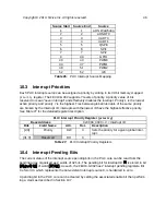
PLIC Interrupt Enable Register 1 (
enable1
) for Hart 0 M-Mode
Base Address
0x0C00_2000
Bits
Field Name
Attr.
Rst.
Description
0
Interrupt 0 Enable
RO
0
Non-existent global interrupt 0 is hard-
wired to zero
1
Interrupt 1 Enable
RW
X
Enable bit for global interrupt 1
2
Interrupt 2 Enable
RW
X
Enable bit for global interrupt 2
…
31
Interrupt 31
Enable
RW
X
Enable bit for global interrupt 31
Table 30:
PLIC Interrupt Enable Register 1 for Hart 0 M-Mode
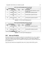
PLIC Interrupt Enable Register 2 (
enable2
) for Hart 0 M-Mode
Base Address
0x0C00_2004
Bits
Field Name
Attr.
Rst.
Description
0
Interrupt 32
Enable
RW
X
Enable bit for global interrupt 32
…
20
Interrupt 52
Enable
RW
X
Enable bit for global interrupt 52
[31:21]
Reserved
RO
0
Table 31:
PLIC Interrupt Enable Register 2 for Hart 0 M-Mode
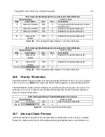
The FE310-G002 supports setting of an interrupt priority threshold via the
threshold
register.
The
threshold
is a
WARL
field, where the FE310-G002 supports a maximum threshold of 7.
The FE310-G002 masks all PLIC interrupts of a priority less than or equal to
threshold
. For
example, a
threshold
value of zero permits all interrupts with non-zero priority, whereas a
value of 7 masks all interrupts.
PLIC Interrupt Priority Threshold Register (
threshold
)
Base Address
0x0C20_0000
[2:0]
Threshold
RW
X
Sets the priority threshold
[31:3]
Reserved
RO
0
Table 32:
PLIC Interrupt Threshold Register
A FE310-G002 hart can perform an interrupt claim by reading the
claim/complete
register
(Table 33), which returns the ID of the highest-priority pending interrupt or zero if there is no
Copyright © 2019, SiFive Inc. All rights reserved.
48
Содержание FE310-G002
Страница 1: ...SiFive FE310 G002 Manual v19p05 SiFive Inc ...
Страница 11: ...Figure 1 FE310 G002 top level block diagram Copyright 2019 SiFive Inc All rights reserved 9 ...
Страница 15: ...Chapter 2 List of Abbreviations and Terms 13 ...
Страница 23: ...Chapter 4 Memory Map The memory map of the FE310 G002 is shown in Table 4 21 ...


