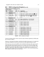
The 4-bit
pwmscale
field scales the PWM counter value before feeding it to the PWM compara-
tors. The value in
pwmscale
is the bit position within the
pwmcount
register of the start of a
cmpwidth
-bit
pwms
field. A value of 0 in
pwmscale
indicates no scaling, and
pwms
would then be
equal to the low
cmpwidth
bits of
pwmcount
. The maximum value of 15 in
pwmscale
corre-
sponds to dividing the clock rate by 2
15
, so for an input bus clock of 16 MHz, the LSB of
pwms
will increment at 488.3 Hz.
The
pwmzerocmp
bit, if set, causes the PWM counter
pwmcount
to be automatically reset to zero
one cycle after the
pwms
counter value matches the compare value in
pwmcmp0
. This is normally
used to set the period of the PWM cycle. This feature can also be used to implement periodic
counter interrupts, where the period is independent of interrupt service time.
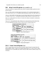
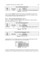
The Scaled PWM Count Register
pwms
reports the
cmpwidth
-bit portion of
pwmcount
which
starts at
pwmscale
, and is what is used for comparison against the
pwmcmp
registers.
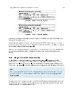
Scaled PWM Count Register (
pwms
)
Register Offset
0x10
Bits
Field Name
Attr.
Rst.
Description
[15:0]
pwms
RW
X
Scaled PWM count register.
cmpwidth
bits wide.
[31:16]
Reserved
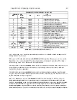
PWM 0 Compare Register (
pwmcmp0
)
Register Offset
0x20
Bits
Field Name
Attr.
Rst.
Description
[15:0]
pwmcmp0
RW
X
PWM 0 Compare Value
[31:16]
Reserved
PWM 1 Compare Register (
pwmcmp1
)
Register Offset
0x24
Bits
Field Name
Attr.
Rst.
Description
[15:0]
pwmcmp1
RW
X
PWM 1 Compare Value
[31:16]
Reserved
Table 92:
Scaled PWM Count Register
Table 93:
PWM 0 Compare Register
Table 94:
PWM 1 Compare Register
Copyright © 2019, SiFive Inc. All rights reserved.
98
Содержание FE310-G002
Страница 1: ...SiFive FE310 G002 Manual v19p05 SiFive Inc ...
Страница 11: ...Figure 1 FE310 G002 top level block diagram Copyright 2019 SiFive Inc All rights reserved 9 ...
Страница 15: ...Chapter 2 List of Abbreviations and Terms 13 ...
Страница 23: ...Chapter 4 Memory Map The memory map of the FE310 G002 is shown in Table 4 21 ...

