Procedure with Startdrive
In order to prevent that the feedback signal input of the fail-safe digital output unintentionally
controls the "standard" functions in the inverter, proceed as follows:
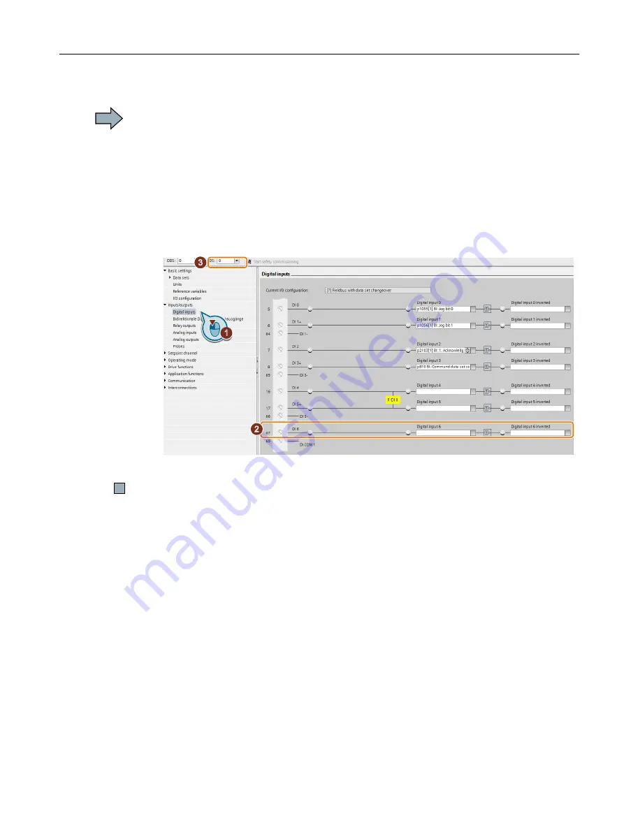
1. Select the digital inputs.
2. Remove the interconnection of the digital input that you use as feedback signal input for
the fail-safe digital output:
– SINAMICS G120 with CU250S-2 Control Unit: Digital input DI 6 (see diagram).
– SINAMICS G120D: Digital input DI 5.
3. If you are using several command data sets (CDS), then remove the interconnection of the
feedback signal input for all CDS.
Figure 5-39 Removing the interconnection of the feedback signal input DI 6 for the CU250S-2
You have now prevented that the feedback signal input of the fail-safe digital output controls
"standard" functions in the inverter.
Commissioning
5.12 Setting extended functions
Safety Integrated - SINAMICS G110M, G120, G120C, G120D and SIMATIC ET 200pro FC-2
Function Manual, 01/2017, FW V4.7 SP6, A5E34261271B AD
203


