4. Set the monitoring time to a value to match your application.
5. Using this signal, the inverter signals that a forced checking procedure (test stop) is required
for the "STO via Power Module terminals" function.
6. Close the screen forms.
You have set the "STO via Power Module terminals" function.
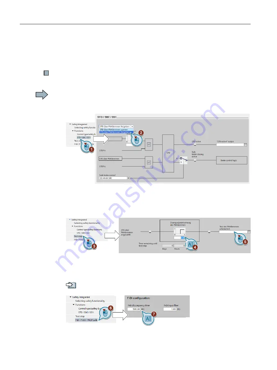
Procedure with Startdrive
Proceed as follows to set the "STO via Power Module terminals" function:
1. Select "STO / SBC / SS1".
2. Select "Enable STO via the PM terminals".
3. Select "Test stop"
4. Set the monitoring time to a value to match your application.
5. Using this signal, the inverter signals that a forced checking procedure (test stop) is required
for the "STO via Power Module terminals" function.
6. Select "F-DI / F-DO / PROFIsafe".
7. Set the discrepancy time (simultaneity monitoring) of the terminals on the Power Module.
The setting not only applies for the terminals of the Power Module, but also for the fail-safe
digital input on the Control Unit for selecting STO.
Setting the filter for fail-safe digital inputs (Page 128)
The "F-DI input filter" has no significance for the terminals on the Power Module.
Commissioning
5.11 Setting basic functions
Safety Integrated - SINAMICS G110M, G120, G120C, G120D and SIMATIC ET 200pro FC-2
134
Function Manual, 01/2017, FW V4.7 SP6, A5E34261271B AD


