Contents
12.2010
Siemens AG
6SE7087-6QX70 (Version AM)
SIMOVERT MASTERDRIVES
Compendium Motion Control
7
8.4
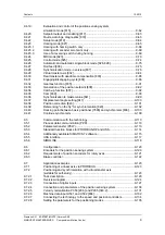
CBC Communications Board......................................................................... 8.4-1
8.4.1
Product description........................................................................................ 8.4-1
8.4.2
Mounting methods / CBC slots ...................................................................... 8.4-4
8.4.2.1
Mounting positions of the CBC in MC Compact PLUS units......................... 8.4-4
8.4.2.2
Mounting positions of the CBC in Compact and chassis units of function
classes MC (CUPM, CUMC) and VC (CUVC) .............................................. 8.4-5
8.4.2.3
Mounting positions of the CBC in Compact type and chassis type units
with the CU of the function classes FC (CU1), VC (CU2) or SC (CU3) ........ 8.4-6
8.4.2.4
Mounting positions of the CBC in VC Compact PLUS units ......................... 8.4-7
8.4.3
Connecting..................................................................................................... 8.4-8
8.4.3.1
Connection of the bus cable .......................................................................... 8.4-9
8.4.3.2
EMC measures ............................................................................................ 8.4-10
8.4.3.3
Bus termination of the CAN bus (jumper S1.2) ........................................... 8.4-13
8.4.3.4
Ground connection (jumper S1.1) ............................................................... 8.4-13
8.4.3.5
Interface X458 / X459 with jumper strip S1 ................................................. 8.4-14
8.4.3.6
Recommended circuits ................................................................................ 8.4-15
8.4.4
Data transfer via the CAN bus..................................................................... 8.4-16
8.4.4.1
General ........................................................................................................ 8.4-16
8.4.4.2
Parameter area (PKW) ................................................................................ 8.4-17
8.4.4.3
Process data area (PZD)............................................................................. 8.4-24
8.4.5
Start-up of the CBC ..................................................................................... 8.4-31
8.4.5.1
Basic parameterization of the units ............................................................. 8.4-32
8.4.5.2
Process-data softwiring in the units............................................................. 8.4-45
8.4.6
Diagnosis and troubleshooting .................................................................... 8.4-52
8.4.6.1
Evaluation of hardware diagnostics............................................................. 8.4-52
8.4.6.2
Fault displays and alarms on the basic unit ................................................ 8.4-54
8.4.6.3
Evaluation of the CBC diagnostic parameter .............................................. 8.4-56
8.4.6.4
Meaning of CBC diagnosis .......................................................................... 8.4-57
8.4.7
Appendix...................................................................................................... 8.4-60
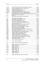
8.5
CBC CANopen communication board........................................................... 8.5-1
8.5.1
Object directory.............................................................................................. 8.5-5
8.5.2
Commissioning the CBC ............................................................................. 8.5-16
8.5.2.1
General settings........................................................................................... 8.5-16
8.5.2.2
NMT state .................................................................................................... 8.5-27
8.5.2.3
Relation between PDO/PZD and SDO/PKW............................................... 8.5-29
8.5.2.4
PDO mapping .............................................................................................. 8.5-34
8.5.3
Manufacturer-specific objects...................................................................... 8.5-48
8.5.3.1
Parameter editing ........................................................................................ 8.5-48
8.5.3.2
Example: Change parameter value with object 4001h................................ 8.5-52
8.5.3.3
Setting factory values (defaults) via CANopen............................................ 8.5-53
8.5.3.4
Changing the baud rate and bus address
(on MASTERDRIVES MC only)................................................................... 8.5-54
8.5.4
Faults and alarms ........................................................................................ 8.5-55
8.5.4.1
Structure of object 1003h (pre-defined error field) ...................................... 8.5-55
8.5.4.2
Error codes .................................................................................................. 8.5-56
8.5.5
Life guarding / node guarding...................................................................... 8.5-59
8.5.6
The state machine ....................................................................................... 8.5-60
8.5.6.1
Control word ................................................................................................ 8.5-61
8.5.6.2
Status word.................................................................................................. 8.5-62
8.5.6.3
Modes of operation...................................................................................... 8.5-64
8.5.7
Description of individual modes................................................................... 8.5-65
8.5.7.1
Profile Position mode................................................................................... 8.5-65
Содержание simovert masterdrives
Страница 1: ...Compendium Edition AN simovert masterdrives Motion Control ...
Страница 2: ......
Страница 13: ......
Страница 197: ...Parameterizing Steps 08 2012 6SE7087 6QX70 Version AN Siemens AG 6 32 Compendium Motion Control SIMOVERT MASTERDRIVES ...
Страница 199: ...Parameterizing Steps 08 2012 6SE7087 6QX70 Version AN Siemens AG 6 34 Compendium Motion Control SIMOVERT MASTERDRIVES ...
Страница 201: ...Parameterizing Steps 08 2012 6SE7087 6QX70 Version AN Siemens AG 6 36 Compendium Motion Control SIMOVERT MASTERDRIVES ...
Страница 203: ...Parameterizing Steps 08 2012 6SE7087 6QX70 Version AN Siemens AG 6 38 Compendium Motion Control SIMOVERT MASTERDRIVES ...
Страница 205: ...Parameterizing Steps 08 2012 6SE7087 6QX70 Version AN Siemens AG 6 40 Compendium Motion Control SIMOVERT MASTERDRIVES ...
Страница 207: ...Parameterizing Steps 08 2012 6SE7087 6QX70 Version AN Siemens AG 6 42 Compendium Motion Control SIMOVERT MASTERDRIVES ...
Страница 209: ...Parameterizing Steps 08 2012 6SE7087 6QX70 Version AN Siemens AG 6 44 Compendium Motion Control SIMOVERT MASTERDRIVES ...
Страница 947: ...08 2012 Siemens AG 6SE7087 6QX70 Version AN SIMOVERT MASTERDRIVES Compendium Motion Control Function Diagrams ...
Страница 1160: ...03 2010 Siemens AG 6SE7087 6QX70 Version AL SIMOVERT MASTERDRIVES Compendium Motion Control General parameter list ...
Страница 1416: ...03 2010 Siemens AG 6SE7087 6QX70 Version AL SIMOVERT MASTERDRIVES Compendium Motion Control Connector list ...
Страница 1446: ...03 2010 Siemens AG 6SE7087 6QX70 Version AL SIMOVERT MASTERDRIVES Compendium Motion Control Binector list ...
Страница 1466: ...03 2010 Siemens AG 6SE7087 6QX70 Version AL SIMOVERT MASTERDRIVES Compendium Motion Control List of function data set parameters ...
Страница 1471: ...03 2010 Siemens AG 6SE7087 6QX70 Version AL SIMOVERT MASTERDRIVES Compendium Motion Control List of binector data set parameters ...
Страница 1535: ......
Страница 1536: ......
Страница 1537: ......
Страница 1538: ......
Страница 1539: ......
Страница 1540: ......
Страница 1541: ......
Страница 1542: ......
Страница 1543: ......
Страница 1546: ......


