55
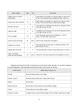
(b) Relevant parameter modification
After the Inertia estimation, some parameters related to control gain performance would be
modified automatically.
Pr.No
Sign
Function description
Setting
range
Unit
PB03
NLP
Resonance suppression low-pass filter
0
~10000
0.1ms
PB05
FFC
Position feed-forward gain
0
~200
%
PB06
GD1
Load to motor inertia ratio
0
~1200
0.1time
PB07
PG1
Position loop gain
4
~1024
rad/s
PB08
VG1
Speed loop gain
40
~9000
rad/s
PB09
VIC
Speed integral gain
1
~1000
ms
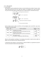
After the calculation completed, users must terminate the
“Auto tuning control panel” in order to
record the relevant parameters. If users already know the low frequency gain and inertia ratio of the
system, they could also set the bandwidth value desired to calculate the optimum value for
controller.
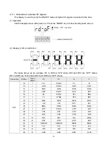
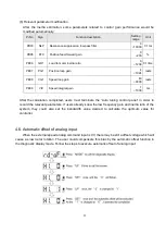
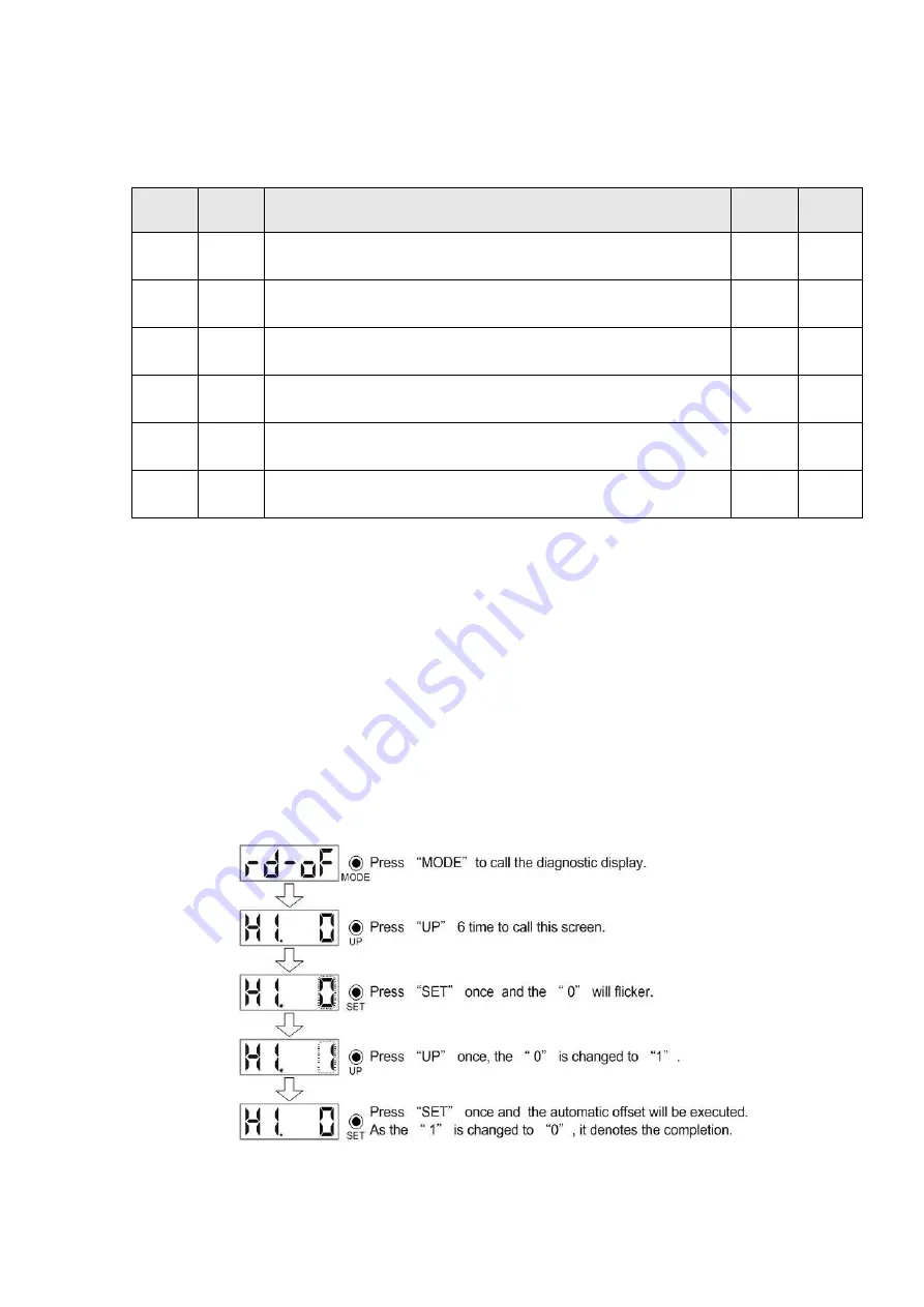
4.6. Automatic offset of analog input
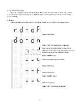
When the external speed analog command input is 0V, there may be still a offset voltage which will
cause a slow motor rotation. The user could compensate this bias by the automatic offset function in
the diagnostic display mode. Follow the steps to execute automatic offset of analog input:
Содержание SDE Series
Страница 13: ...5 1 6 Function block diagram ...
Страница 26: ...18 3 3 3 CN1 pin name list ...
Страница 212: ...204 SDE 075A2U SDE 100A2U 750W 1KW unit mm Dimensions of the servo drive may be revised without prior notice ...
Страница 223: ...215 SME L040 SME L075 SME L100 SME L150 ...
Страница 224: ...216 SME L200 SME L300 SME M100 SME M150 Continuous running range ...
Страница 225: ...217 SME M200 SME M300 NOTE These characteristic plots above are measured in case of 3φ 200 240V power supplied ...
Страница 227: ...219 ...
Страница 231: ...223 4 Wiring example with peripheral equipment CN2 Encoder socket ...
Страница 242: ...234 12 4 Version information Version V1 01 Issue date Aug 2017 Proofreader Yaochou Shu ...

