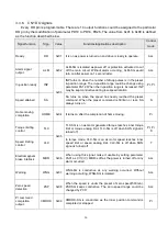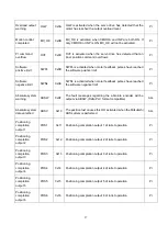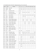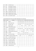
14
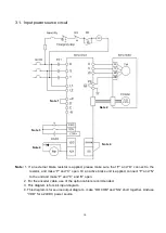
3.1. Input power source circuit
Note:
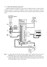
1. If an external brake resistor is applied, please make sure that
“P” and “D” connect to the
resistor, and make
“P” and “C” open. Or an active brake unit is applied, connect “P” and “N”
to the unit and make
“P” and “C” and “D” open.
Note:
2. For the encoder cable, use of the option cable is recommended.
Note:
3. This diagram is for sink input diagram.
Note:
4. This diagram is for source output diagram, .make
“ DOCOM” and “SG” short together. And use
“VDD” for a 24VDC power source.
Note 2
Note 1
Note 3
Note 4
Note 4
Содержание SDE Series
Страница 13: ...5 1 6 Function block diagram ...
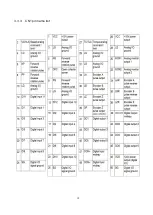
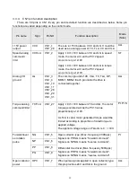
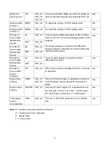
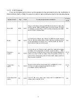
Страница 26: ...18 3 3 3 CN1 pin name list ...
Страница 212: ...204 SDE 075A2U SDE 100A2U 750W 1KW unit mm Dimensions of the servo drive may be revised without prior notice ...
Страница 223: ...215 SME L040 SME L075 SME L100 SME L150 ...
Страница 224: ...216 SME L200 SME L300 SME M100 SME M150 Continuous running range ...
Страница 225: ...217 SME M200 SME M300 NOTE These characteristic plots above are measured in case of 3φ 200 240V power supplied ...
Страница 227: ...219 ...
Страница 231: ...223 4 Wiring example with peripheral equipment CN2 Encoder socket ...
Страница 242: ...234 12 4 Version information Version V1 01 Issue date Aug 2017 Proofreader Yaochou Shu ...


