SMD 989
– User Manual
Page 13 (105)
Hardware Overview
The SMD 989 consists of a chassis with two bays which can house individually configured
modulators. There are two different modulator options including the SMD 910 or SMD912(A).
These options are described in the next section of this manual. Each modulator option can be
configured to support either IF or L-band outputs. The modulators support all DVB-S/S2
modulation types from QPSK to 64 APSK. The SMD 910 modulator can be upgraded to support
multistream outputs with streams input to one of the four ASI ports or IP interface. The SMD912
modulator can be upgraded to support Turbo PSK advanced modulation. This section of the
manual describes the chassis and hardware options available.
SMD 989 Chassis and Controller
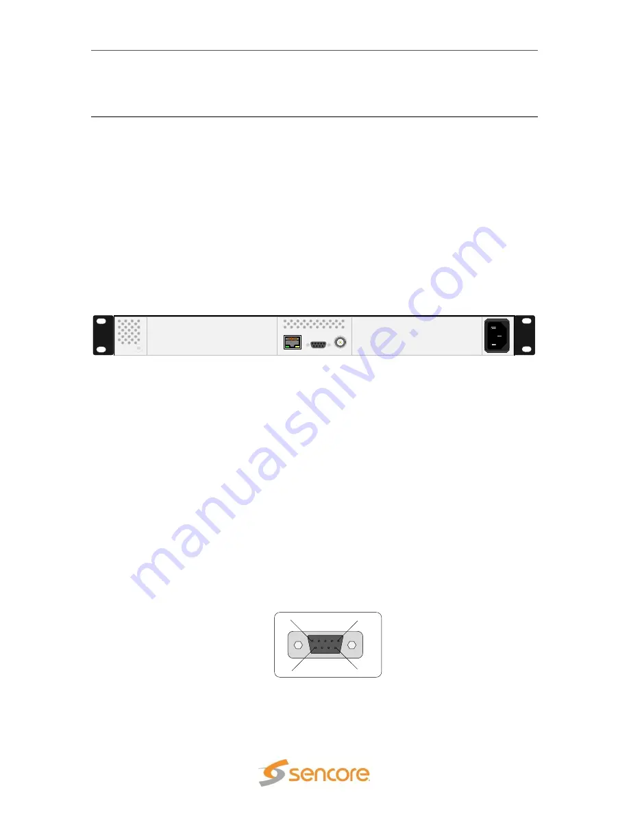
The Sencore SMD 989 satellite modulator platform can be configured in multiple hardware
configurations. The two bays with the controller located in the middle of the chassis as shown in
Figure 1.
CONTROL
REF IN
ALARM
B
A
Y
2
B
A
Y
1
1
0
0
-2
4
0
V
A
C
, 4
7
-6
3
H
z
, 2
0
0
W
The controller module hosts the graphical user interface along with the relays and 10 MHz input
reference. Looking at the rear of the chassis, the left slot is bay 1 and the right slot is bay 2.
Each bay is independently controlled and operated. Therefore each bay needs to be configured
separately in order to ensure the expected operation.
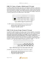
The SMD 989 platform offers eight modulation options. The modulation module is the SMD 910
which includes an MPEGoIP input via RJ45, four ASI inputs via BNC connectors, and an IF
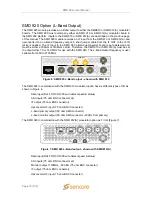
output via a BNC connector. The SMD 910 option can be configured with an optional L-band
output module, the SMD 920 which includes and L-band output via an SMA connector. The other
licenses available are software licenses enabling features for bitrates, DVB-S2, and multistream.
Alarm Contact Closure
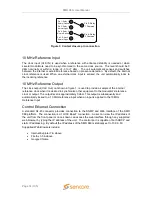
The
Alarm
contact closure output connector allows a user to configure two separate contacts that
can be used to drive external alarm indicators (sirens, flashlight etc.) or can be used to connect to
a redundancy switching system. The pinout in Figure 3 shows the relays in a de-energized state.
When the SMD 989 is on the relays energize. This allows the possibility to monitor the state of
the relays if the unit losses power the relays de-energize and a redundant unit can be activated.
Figure 1: Basic SMD 989 platform
Figure 2: Contact closure alarm output connector
ALARM
1
6
5
9


