SMD 989
– User Manual
Page 21 (105)
Installation
General Considerations
This section describes the installation procedure for the SMD 989.
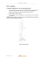
Rack size
The chassis is designed to be installed in a standard 19-inch rack. The SMD 989 occupies 1RU
of rack space. All of the cable connections are located on the rear of the unit.
Ventilation
The SMD 989 is cooled via forced induction through the front of the unit and exhausted through
the vents in the rear. The SMD 989 is equipped with a temperature monitors to ensure operating
temperature is maintained.
Power Connection
Using the proper power connections is vital to the safe operation of the SMD 989. Only use the
supplied 3-prong power connector or one with equal specifications.
AC Power Connection
The SMD 989 is capable of either operating on 120V or 240V systems. The power supply will
automatically detect the system it is connected to. To hook up the power use the following steps:
1. Locate the AC power cord included with the SMD 989.
2. Plug the female end of the power cord (end with no prongs) into the back of the unit.
3. Locate a protected outlet (usually inside of the rack) to plug the male end of the power
cable into.
AC Dual Redundant Power Connection (optional)
The Dual Redundant option allows the SMD 989 to be powered by two separate AC supplies
either operating on 120V or 240V systems. The power supply will automatically detect the
system it is connected to. To hook up the power use the following steps:
1. Locate the AC power cords included with the SMD 989.
2. Plug the female end of the power cords (end with no prongs) into the back of the unit.
3. Locate a protected outlet (usually inside of the rack) to plug the male end of the power
cord into.
DC Dual Redundant Power Connection (optional)
The Dual Redundant option allows the SMD 989 to be powered by two separate DC supplies
operating on a
-
48VDC system. To hook up the power use the following steps:
1. Connect the negative 48VDC to the terminal labeled -48V.
2. Connect ground to the terminal labeled 0V

