Mach-DSP User’s Manual
Document Number: MACH-DSP-9021
Page 84
www.ScannerMAX.com
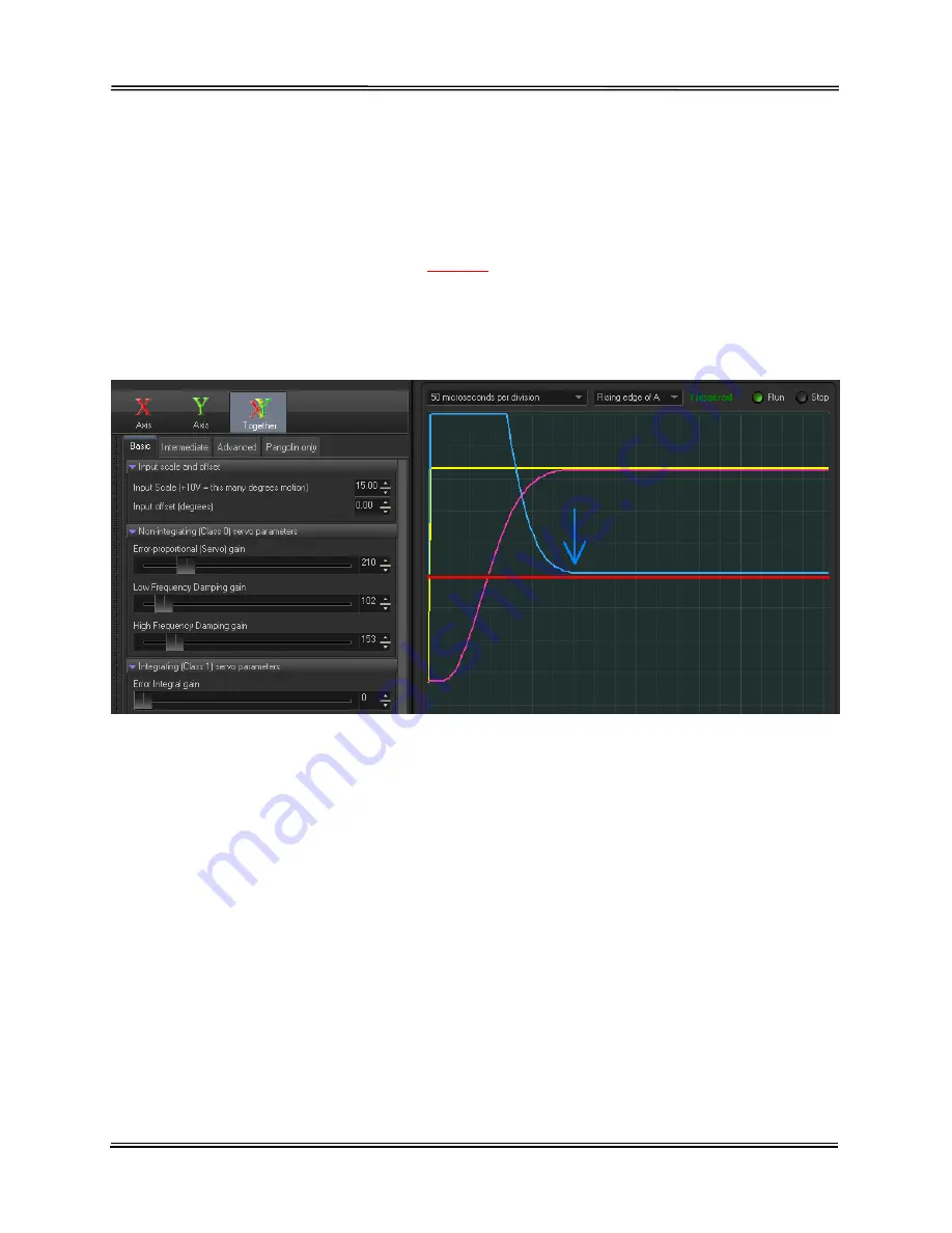
Below you see a screen-shot from the Mach-DSP program. This screen shot was made
after example rough PD tuning discussed in section 10.2. In this screen shot, the
scanner is tuned for approximately 350 microsecond small steps (as can be seen with
the blue arrow). In the example rough tuning above, a step of 2.0 degrees was input,
and the blue trace shows Position Error, having a scale factor of 0.1 degrees per
division.
In this screen shot, we have placed a
red line
on the zero axis, to highlight how the blue
trace does not quite go to zero. Since this particular view shows 0.1 degrees per
division, and since the blue line is approximately 1/10 the way upward on a division, this
indicates that an error remains of approximately 0.01 degrees, or 175 microradians of
error.
This error may be reduced by further increasing Error-proportional (Servo) gain, along
with appropriate amounts of Low Frequency Damping and High Frequency Damping.
Indeed, the particular scanner we were using while making all of these screen shots is
capable of achieving step times of 75 microseconds, and so by tuning to 350
microseconds, there is a lot of performance remaining, and a lot of room remaining on
the sliders for further tuning increases.
However, increasing Servo gain also increases servo bandwidth (along with noise), and
if the particular application did not need any greater bandwidth, then perhaps this would
not be a very good solution.
Therefore, to maintain the current servo bandwidth and eliminate the position error, the
Error Integral gain can be increased. This is illustrated in the next screen shot. Note that
we have increased the time-base to 2 milliseconds per division, and increased Error
Integral gain to only 3.


