Tel: 886.2.2175 2930 Email: [email protected]
www.salukitec.com
198
7.4.
High-accuracy Measurement Calibration
The calibration accuracy depends on the selected calibration type, calibration kit quality and calibration process. This section mainly
discusses how to perform high-accuracy calibration.
1) Measurement reference plane
The tested device is not directly connected to the port of the analyzer in most of measurements. Instead, it is connected through the
test fixture or cable. The connection point of the tested device must be calibrated to realize the highest measurement accuracy. This
point is called the measurement reference plane. If the measurement reference plane is calibrated, the error related to the
measurement composition (such as the cable, test fixture and adapter between the analyzer port and reference plane) can be
measured and eliminated.
2) Influence of calibration kit
Under normal conditions, the calibration standard of the calibration kit is the same as the connector type standard of the tested device.
In some cases, however, the calibration kit corresponding to the connector type of the tested device is not provided. For example, the
port size of the tested device is 2.4mm, but the connector size of the analyzer and calibration kit is 3.5mm. If the 2.4mm calibration kit
is used for calibration and the 2.4mm/3.5mm adapter is used in measurement, the measurement error will be obvious, especially in
reflection measurement, as the adapter is not calibrated. If the applied calibration kit is different from the calibration kit specified for
calibration, the calibration accuracy will be reduced. The degree of accuracy reduction depends on the difference between the
specified calibration kit and actual calibration kit.
3) Accuracy of interpolation measurement
If the instrument settings are different from calibration settings, calibration data can be automatically interpolated into the analyzer. In
this case, the measurement accuracy cannot be predicted and may drop greatly or not be affected. The measurement error must be
determined depending on the actual situation. If the phase shift added by two measurement points exceeds 180 degrees, the
measurement accuracy will drop greatly as the correct phase data cannot be interpolated. Generally, the probability of accuracy
reduction may increase as a result of interpolation in the following cases:
When the frequency span between measurement points is increased;
When the frequency span between measurement points is too large;
When the measurement frequency is high, especially above 10GHz.
4) Influence of power level
The power level must not be changed after calibration in order to realize the highest accuracy of error correction. However, if the
power level is changed under the same conditions as the attenuator settings in calibration, the accuracy of S-parameter measurement
only declines a little. If the attenuator settings are changed, the accuracy of error correction will decline further.
5) System impedance
The system impedance must be changed in measurement of the impedance device (not 50Ω) such as the waveguide device. The
default system impedance is 50Ω.
a) Setting of system impedance
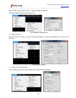
Menu path: [System] > [Configuration] > [System impedance...].
Enter the system impedance value in the [Impedance] box and click [OK] to close the dialog box.
6) Port extension
The measurement reference plane may be changed as a result of connection of the cable, adapter or fixture after calibration, which
may lead to increase of the phase shift. In this case, the additional phase offset can be compensated by means of port extension. Port
extension is the simplest method to compensate the additional phase shift between the calibration plane and tested device plane, but
cannot be used to compensate the loss and mismatch of the path between the calibration plane and tested device plane. Therefore,


