


Tel: 886.2.2175 2930 Email: [email protected]
www.salukitec.com
177
1.0 corresponds to the light speed in vacuum.
0.66 corresponds to the typical light speed in the polyethylene medium.
0.70 corresponds to the typical light speed in the Teflon medium.
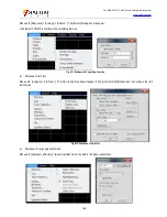
Fig. 6.11 Setting of Electrical Delay
2) Electrical movement reference plane
Menu path: [Calibration] > [Port extension...]. Select the [Port extension on/OFF] check box.
Add the port extension value in the reference plane to be extended.
Select a value between 0 and 1.0 in the [Speed factor] box as the relative speed of the added cable or medium after calibration. Then
click [OK].
1.0 corresponds to the light speed in vacuum.
0.66 corresponds to the typical light speed in the polyethylene medium.
0.70 corresponds to the typical light speed in the Teflon medium.
You can perform the following operation to check whether the sufficient delay is added:
Connect one short-circuit device.
Adjust the port extension until the phase correspondingly becomes flat.
Determine the deviation delay of the standard short-circuit device.
The delay time of the majority of short-circuit calibration kits is not zero. Therefore, the delay error caused by this method is twice that
of the short-circuit device. Determine the deviation delay of the standard short-circuit device according to the definition of the
inspection standards.
3) phase offset measurement
Menu path: [Response] > [Scale] > [phase offset...].
Enter the value in the [phase offset] dialog box or select the required value with the arrow.
4) Inspection of mixing
Menu path: [Stimulus] > [Sweep] > [Number of sweep points].
Select one value in the list, or click [Custom...], and enter the value smaller than the current value through the number keys of the


