PART V TROUBLESHOOTING
5-26
ENGLISH
Electronic
Cell
Front Panel
Cell Ground
Contact Terminal
Unit Ground
Contact Terminal
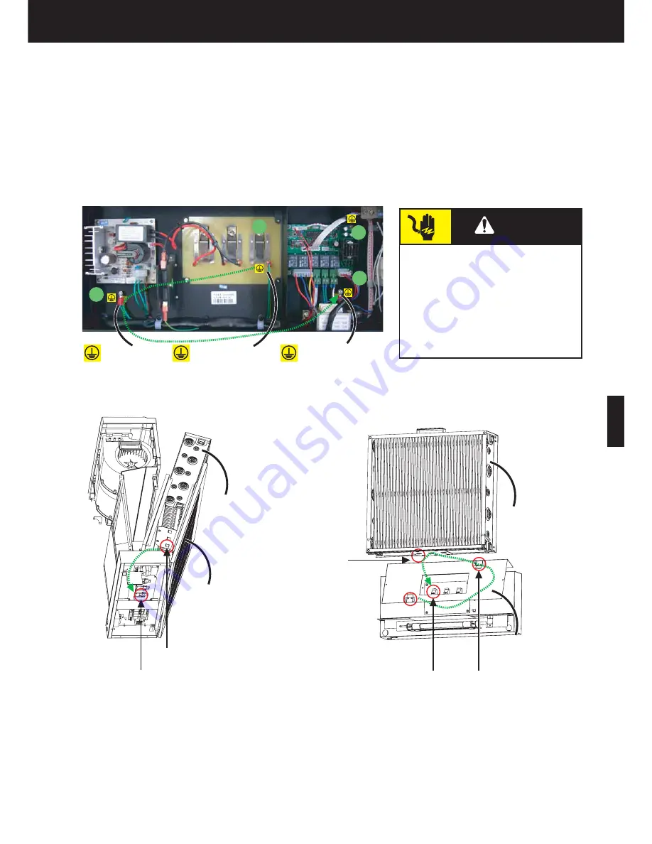
Unit electrical ground system
It is necessary to understand how the whole unit is grounded when you try to fix electrical system problems of the unit.
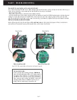
When you open the bottom plate, you will see the unit ground terminal (1#), a ground screw (2#) under the power supply,
another ground screw (3#) under the main circuit board and the main circuit board ground screw (4#) (Fig. 5.10-4).
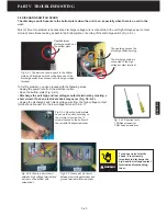
1. The front panel, cell frame, pre filter and discharge switch are grounded by the unit ground terminal and through the
ground wire to the ground screw 2# (Fig. 5.10-5).
2. The power supply is grounded to the ground screw 2# through its ground wire.
3. The main circuit board is grounded by its ground screw 4#.
4. The motor is grounded by ground screw 3#.
5. Finally, all the electrical parts are grounded through metal casing to the ground screw 3#, which is connected with
power cord ground wire.
Electronic
Cell
Front Panel
Cell Ground
Contact Terminal
Front Panel
Ground Contact
Plate
Front Panel
Ground Contact
Plate
Unit Ground
Contact Terminal
Fig. 5.10-4 The eletrical ground system of the unit.
Fig. 5.10-5 The front panel is grounded through the two ground contact plates.
Motor ground wire
and power cord
ground wire
Front panel, Pre
filter, cell frame,
carbon filter and
discharge switch
ground
Bottom Ground
Screw
WARNING
To reduce the risk of electric shock,
this equipment has a grounding type
plug that has a third (grounding) pin.
This plug will only fit into a grounded
power outlet. If the plug does not fit
into the outlet, contact a qualified
person to install the proper outlet. Do
not alter the plug in any way.
1
2
3
4
Содержание R200T
Страница 69: ...ENGLISH NOTES ...

