ENGLISH
PART III ELECTRICAL SYSTEM OF THE UNIT
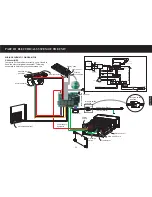
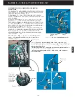
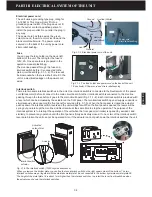
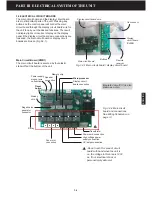
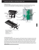
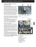
WIRING SCHEMATIC DIAGRAM FOR
J200xxx UNITS
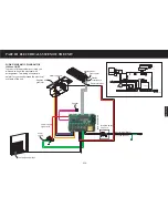
In order to fix the problems correctly, you
will need to know the electrical wire
arrangement. This wiring schematic is
helpful for you to understand the electrical
systems of the unit.
Interlock switch
and Fuse
Power supply
signal wire
Fuse
Live line (White)
Neutral wire (Black)
Speaker
Power
supply
Main circuit board-A
Motor capacitor
Negative ion
generator
Display
circuit board
Odor sensor
Remote receiver
Display panel
UV lamp and ballast
Interlock switch
Interlock switch
Transformer
JZ4
JZ17
JZ11
JZ15 JZ16
JZ10
JZ18
JZ6
JZ8
JZ1
Blue
Black
White
White
Green
Y. Green
Yellow Green
Yellow green
Fuse
Black
White
Pink white
Electrostatic
discharge switch
High voltage
generator
Ver.2.0
A
B
C
D
E
F
Electronic cell
Black
(-)
Red
(+)
Fan motor
UV lamp and ballast
Collector
White
White
H
M
L
C
Gas sensor
Remote control receiver
Negative ion
generator
Ionizer
Black
Black
Red
Red
Red
Speaker
Green
Green
Yellow
Red
Green
Power supply board
Control board
120V/60Hz
H M L C
3-1A
Содержание R200T
Страница 69: ...ENGLISH NOTES ...

