H
L
G
ENGLISH
PART III ELECTRICAL SYSTEM OF THE UNIT
DIFFERENT WIRING ARRANGEMENT
To simplify the wiring arrangement, the units will have
some different wiring arrangements.
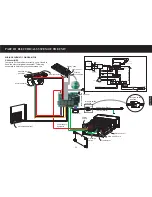
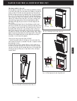
3-1B
Fig. 3-1 Units starting with ser.#J200xxx.
1-High voltage wire of power supply
2-Low voltage wire of power supply
3-Ground wire of power supply
4-Power supply signal wire
5-Power supply cord wire
6-Voltage wire of discharge switch
7-Ground wire of discharge switch
8-Ground wire to the bottom
9-Ground wire of power cord
*** The transformer is located on the main
circuit board and the power supply ground
wire is connected to the unit ground terminal.
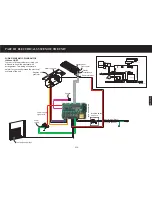
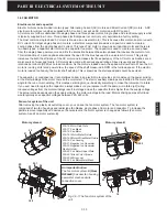
Fig. 3-2 Units starting with ser. #R200xxxB~D.
1-High voltage wire of power supply
2-Low voltage wire of power supply
3-Ground wire of power supply
4-Power supply signal wire
5-Power supply cord wire
6-Voltage wire of discharge switch
7-Ground wire of discharge switch
8-Ground wire to the bottom
9-Ground wire of power cord
10-Motor ground wire
*** The transformer is separated from the main
circuit board and the power supply ground wire is
grounded through the ground wire. The motor
ground wire is secured with power cord ground
wire.
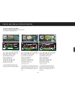
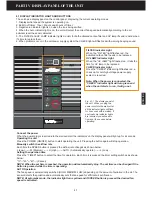
Fig. 3-3 Units starting with ser.# R200xxxE.
1-High voltage wire of power supply
2-Low voltage wire of power supply
3-Ground wire of power supply
4-Power supply signal wire
5-Power supply cord wire
6-Voltage wire of discharge switch
7-Ground wire of discharge switch
8-Ground wire to the bottom
9-Ground wire of power cord
10-Motor ground wire
*** The transformer is separated from the
main circuit board and the power supply
ground wire is directly grounded. The motor
ground wire is secured with power cord
ground wire.
3
1
2
3
2
4
6
5
8
7
9
Main circuit board-A
Main circuit board-B
Main circuit board-B
4
3
5
6
9
7
8
2
2
H
L
G
1
1
1
3
4
5
6
7
8
9 10
4
5
6
7
8
10
9
H
L
G
Содержание R200T
Страница 69: ...ENGLISH NOTES ...

