PART III ELECTRICAL SYSTEM OF THE UNIT
3-7
ENGLISH
3.4 DISCHARGE SWITCH
The electronic cell will normally maintain a painfully high voltage charge when you pull out the cell without stopping the
unit. In fact, the high voltage power supply is designed to discharge the cell automatically. To discharge the cell
automatically, the power supply needs 3-6 seconds after stopping the operation. It means that the cell will be no
charge if the customer stops the operation before taking out the cell.
The problem is some customers do not follow the notice instructions on the stickers or in the manual, opening the front
panel without stopping the unit and pulling out the cell quickly. To solve this problem, the discharge switch is added to
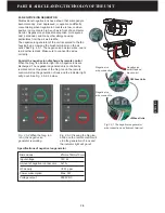
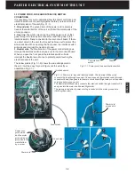
the unit to discharge the remaining charge on the cell when you take out the cell without stopping the operation. The
discharge switch has two wires. One is voltage wire which is connecting the low voltage wire of the power supply
through the unit power contact terminal. Another is ground wire which is grounded through the unit ground terminal. If
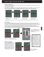
the lever of the switch is pressed down by the front panel the discharge switch does not work. It is because of the
voltage wire separation from the ground wire. However, as the front panel is opened and the switch lever is sprung out
the voltage wire is connecting the ground wire to create a short circuit (direct connection) between the power supply
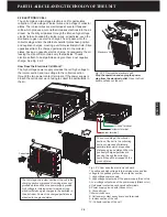
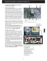
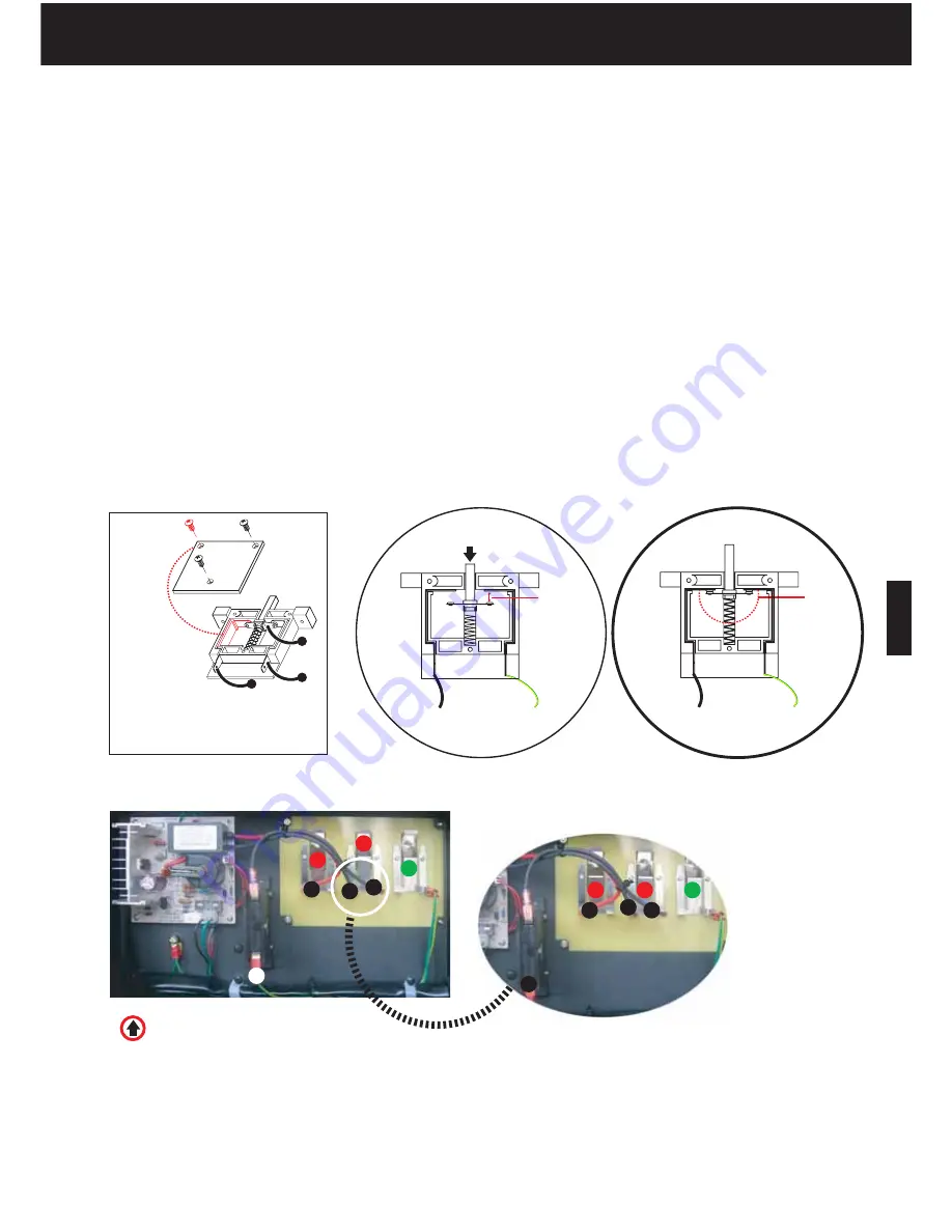
and the ground to discharge the collector section of the cell (Fig. 3.4-1).
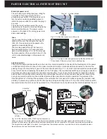
Unfortunately, the discharge switch has only one voltage contact plate, it means the discharge switch cannot
discharge the ionizer and collector section of the cell at the same time. Because of the much more remaining charge
on the collector plates, generally it is recommended that the discharge switch should connect the low voltage contact
terminal to discharge the cell collector section. Another important reason is if the discharge switch is connected to the
high voltage contact terminal, trying to discharge the ionizer section, there will be sparks around the discharge switch
as the voltage plate inside the switch have to sustain very high voltages ( 7.5-8KV). For more information, see
5.9
DISCHARGE SWITCH SPARK
.
If the unit is powered on but the discharge switch lever is not pushed down the CHECK indicator light on the display
panel will flash because of the short between the switch and the power supply low voltage wire (Fig. 3.4-1).
Fig. 3.4-1 Discharge switch
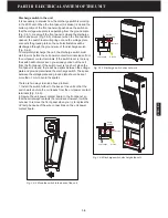
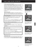
Fig. 3.4-2 The discharge switch is connected to the low voltage power contact
terminal to discharge the collector section of the cell.
1-Unit high voltage contact terminal
2-Unit low voltage contact terminal
3-Unit ground terminal
4-High voltage wire of power supply
5-Low voltage wire of power supply
6-Voltage wire of discharge switch
7-Ground wire
1
3
2
1. Contact plate
2.Voltage plate
3. Ground plate
Low voltage
Separated
Ground
Low voltage
Ground
Short circuit
1
4
4
7
7
6
6
5
5
2
3
1
2
3
Switch
not working
Switch
working
Sometimes,
spark occurs
between
screw and
voltage plate.
Switch Lever
Содержание R200T
Страница 69: ...ENGLISH NOTES ...

