CHAPTER 30 INSTRUCTION SET
Page 855 of 920
Note 1.
Number of CPU clocks (f
CLK
) when the internal RAM area, SFR area, or extended SFR area is accessed, or when no
data is accessed.
Note 2.
Number of CPU clocks (f
CLK
) when the code flash memory is accessed, or when the data flash memory is accessed by
an 8-bit instruction.
Note 3.
This indicates the number of clocks “when condition is not met/when condition is met”.
Note 4.
n indicates the number of register banks (n = 0 to 3)
Remark
Number of clock is when program exists in the internal ROM (flash memory) area. If fetching the instruction from the
internal RAM area, the number becomes double number plus 3 clocks at a maximum.
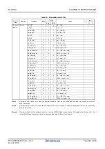
Table 30 - 22 Operation List (18/18)
Instruction
Group
Mnemonic
Operands
Bytes
Clocks
Clocks
Flag
Z
AC
CY
Conditional
branch
BF
saddr.bit, $addr20
4
—
PC
←
PC + 4 + jdisp8 if (saddr).bit = 0
sfr.bit, $addr20
4
3/5
—
PC
←
PC + 4 + jdisp8 if sfr.bit = 0
A.bit, $addr20
3
3/5
—
PC
←
PC + 3 + jdisp8 if A.bit = 0
PSW.bit, $addr20
4
3/5
—
PC
←
PC + 4 + jdisp8 if PSW.bit = 0
[HL].bit, $addr20
3
3/5
6/7
PC
←
PC + 3 + jdisp8 if (HL).bit = 0
ES:[HL].bit, $addr20
4
4/6
7/8
PC
←
PC + 4 + jdisp8 if (ES, HL).bit = 0
BTCLR
saddr.bit, $addr20
4
3/5
—
PC
←
PC + 4 + jdisp8 if (saddr).bit = 1
then reset (saddr).bit
sfr.bit, $addr20
4
3/5
—
PC
←
PC + 4 + jdisp8 if sfr.bit = 1
then reset sfr.bit
A.bit, $addr20
3
3/5
—
PC
←
PC + 3 + jdisp8 if A.bit = 1
then reset A.bit
PSW.bit, $addr20
4
3/5
—
PC
←
PC + 4 + jdisp8 if PSW.bit = 1
then reset PSW.bit
×
×
×
[HL].bit, $addr20
3
3/5
—
PC
←
PC + 3 + jdisp8 if (HL).bit = 1
then reset (HL).bit
ES:[HL].bit, $addr20
4
4/6
—
PC
←
PC + 4 + jdisp8 if (ES, HL).bit = 1
then reset (ES, HL).bit
Conditional
skip
SKC
—
2
1
—
Next instruction skip if CY = 1
SKNC
—
2
1
—
Next instruction skip if CY = 0
SKZ
—
2
1
—
Next instruction skip if Z = 1
SKNZ
—
2
1
—
Next instruction skip if Z = 0
SKH
—
2
1
—
Next instruction skip if (Z
∨
CY) = 0
SKNH
—
2
1
—
Next instruction skip if (Z
∨
CY) = 1
CPU control
SEL
RBn
2
1
—
RBS[1:0]
←
n
NOP
—
1
1
—
No Operation
EI
—
3
4
—
IE
←
1 (Enable Interrupt)
DI
—
3
4
—
IE
←
0 (Disable Interrupt)
HALT
—
2
3
—
Set HALT Mode
STOP
—
2
3
—
Set STOP Mode
Содержание RL78/G1H
Страница 941: ...R01UH0575EJ0120 RL78 G1H...


