


CHAPTER 12 WATCHDOG TIMER
Page 277 of 920
Caution 4. The operation of the watchdog timer in the HALT and STOP modes differs as follows
depending on the set value of bit 0 (WDSTBYON) of the option byte (000C0H).
If WDSTBYON = 0, the watchdog timer resumes counting after the HALT or STOP mode is
released. At this time, the counter is cleared to 0 and counting starts.
When operating with the X1 oscillation clock after releasing the STOP mode, the CPU starts
operating after the oscillation stabilization time has elapsed.
Therefore, if the period between the STOP mode release and the watchdog timer overflow is
short, an overflow occurs during the oscillation stabilization time, causing a reset.
Consequently, set the overflow time in consideration of the oscillation stabilization time when
operating with the X1 oscillation clock and when the watchdog timer is to be cleared after the
STOP mode release by an interval interrupt.
12.4.2
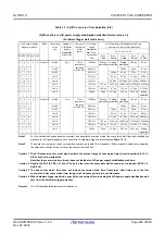
Setting overflow time of watchdog timer
Set the overflow time of the watchdog timer by using bits 3 to 1 (WDCS2 to WDCS0) of the option byte
(000C0H).
If an overflow occurs, an internal reset signal is generated. The present count is cleared and the watchdog timer
starts counting again by writing “ACH” to the watchdog timer enable register (WDTE) during the window open
period before the overflow time.
The following overflow times can be set.
Remark
f
IL
: Low-speed on-chip oscillator clock frequency
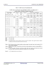
Status
WDSTBYON = 0
WDSTBYON = 1
In HALT mode
Watchdog timer operation stops.
Watchdog timer operation continues.
In STOP mode
In SNOOZE mode
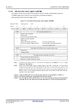
Table 12 - 3 Setting of Overflow Time of Watchdog Timer
WDCS2
WDCS1
WDCS0
Overflow Time of Watchdog Timer
(f
IL
= 17.25 kHz (MAX.))
0
0
0
2
6
/f
IL
(3.71 ms)
0
0
1
2
7
/f
IL
(7.42 ms)
0
1
0
2
8
/f
IL
(14.84 ms)
0
1
1
2
9
/f
IL
(29.68 ms)
1
0
0
2
11
/f
IL
(118.72 ms)
1
0
1
2
13
/f
IL
(474.89 ms)
1
1
0
2
14
/f
IL
(949.79 ms)
1
1
1
2
16
/f
IL
(3799.18 ms)
Содержание RL78/G1H
Страница 941: ...R01UH0575EJ0120 RL78 G1H...


