


RL78/G1H
CHAPTER 18 RF TRANSCEIVER
Page 589 of 920
(23) Time stamp registers 0 and 1 (BBTSTAMP0, BBTSTAMP1)
These registers are used to store the timer values upon the packet data receive start, upon the completion
of the packet data reception, or upon completion of the packet data transmission. The respective time
stamps of receive/transmit are stored. Therefore, the read value can be selected among the values of the
receive start stamp, receive completion stamp, and the transmission stamp by using the stamp value read
switch bit.
The timer count value upon completion of receive is automatically stored in the time stamp register while the
stamp value is retained until the next packet receive completion. The time stamp value corresponding to the
save bank which is specified by the receive data save bank select bit is read out when reading.
In addition, the timer count upon completion of the transmission is automatically stored in the time stamp
register.
The stamp value is retained until the next packet transmission completion. However, the transmission time
stamp value is not updated upon automatic ACK reply.
The BBTSTAMP0 and BBTSTAMP1 registers are read by the serial interface in 8-bit units.
Reset signal generation clears these registers to 0000H.
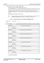
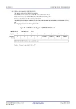
Figure 18 - 31 Time Stamp Register 0 (BBTSTAMP0) Format
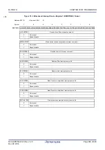
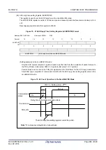
Figure 18 - 32 Time Stamp Register 1 (BBTSTAMP1) Format
Address: 0031H, 0030H
After reset: 0000H
R
Symbol
15
14
13
12
11
10
9
8
BBTSTAM
P0
7
6
5
4
3
2
1
0
BBTSTAMP0
Lower bits of the 32-bit timer (bits 15 to 0)
Address: 0033H, 0032H
After reset: 0000H
R
Symbol
15
14
13
12
11
10
9
8
BBTSTAM
P1
7
6
5
4
3
2
1
0
BBTSTAMP1
Lower bits of the 32-bit timer (bits 31 to 16)
Содержание RL78/G1H
Страница 941: ...R01UH0575EJ0120 RL78 G1H...


