


CHAPTER 7 TIMER ARRAY UNIT
Page 156 of 920
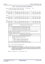
Figure 7 - 13 Format of Timer mode register mn (TMRmn) (2/4)
(Bit 11 of TMRmn (n = 2))
(Bit 11 of TMRmn (n = 1, 3))
Note
Bit 11 is fixed at 0 of read only, write is ignored.
Remark
m: Unit number (m = 0, 1), n: Channel number (n = 0 to 3)
Address: F0190H, F0191H (TMR00) to F0196H, F0197H (TMR03),
After reset: 0000H
F01D0H, F01D1H (TMR10) to F01D6H, F01D7H (TMR13)
Symbol
15
14
13
12
11
10
9
8
7
6
5
4
3
2
1
0
Symbol
15
14
13
12
11
10
9
8
7
6
5
4
3
2
1
0
Symbol
15
14
13
12
11
10
9
8
7
6
5
4
3
2
1
0
MASTERmn
Selection between using channel n independently or
simultaneously with another channel (as a slave or master)
0
Operates in independent channel operation function or as slave channel in simultaneous channel
operation function.
1
Operates as master channel in simultaneous channel operation function.
Only the channel 2 can be set as a master channel (MASTERmn = 1).
Be sure to use channel 0 is fixed to 0 (regardless of the bit setting, channel 0 operates as master, because it is the
highest channel).
Clear the MASTERmn bit to 0 for a channel that is used with the independent channel operation function.
SPLITmn
Selection of 8 or 16-bit timer operation for channels 1 and 3
0
Operates as 16-bit timer.
(Operates in independent channel operation function or as slave channel in simultaneous channel
operation function.)
1
Operates as 8-bit timer.
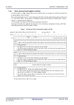
STS
mn2
STS
mn1
STS
mn0
Setting of start trigger or capture trigger of channel n
0
0
0
Only software trigger start is valid (other trigger sources are unselected).
0
0
1
Valid edge of the TImn pin input is used as both the start trigger and capture trigger.
0
1
0
Both the edges of the TImn pin input are used as a start trigger and a capture trigger.
1
0
0
Interrupt signal of the master channel is used (when the channel is used as a slave channel with
the simultaneous channel operation function).
Other than above
Setting prohibited
Содержание RL78/G1H
Страница 941: ...R01UH0575EJ0120 RL78 G1H...


