


CHAPTER 14 SERIAL ARRAY UNIT
Page 363 of 920
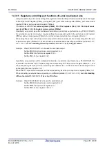
Figure 14 - 31 Flowchart of Master Transmission (in Continuous Transmission Mode)
Note
For the initial setting, refer to
.(Select buffer empty interrupt)
Remark
<1> to <6> in the figure correspond to <1> to <6> in Figure 14 - 30 Timing Chart of Master Transmission (in Continuous
Transmission Mode) (Type 1: DAPmn = 0, CKPmn = 0).
SAU default setting
Starting setting
Wait for transmit completes
Clear interrupt request flag (XXIF), reset interrupt mask (XXMK) and set
interrupt enable (EI).
Writing transmit data to
SIOp (= SDRmn [7:0])
Yes
No
Setting transmit data
Set data for transmission and the number of data . Clear communication end flag
(Storage area, Transmission data pointer, Number of communication data and
Communication end flag are optionally set on the internal RAM by the software )
Enables interrupt
Writing transmit data to
SIOp (= SDRmn [7:0])
Read transmit data from storage area and write it
to SIOp. Update transmit data pointer.
Writing to SIOp makes SOp
and SCKp signals out
(communication starts)
Number of
communication data
>
0?
Buffer empty/transfer end interrupt
When transfer end interrupt is generated, it
moves to interrupt processing routine.
No
If transmit data is left, read them from storage
area then write into SIOp, and update transmit
data pointer and number of transmit data.
If no more transmit data, clear MDmn bit if it’s
set. If not, finish.
Check completion of transmission by
verifying transmit end flag
Yes
End of communication
RETI
Transmission completed?
Disable interrupt (MASK)
Communication
continued?
Subtract -1 from number of
transmit data
Yes
No
MDmn = 1?
Clear MDmn0 bit to 0
Sets communication
completion interrupt flag
Yes
No
<1>
<2>
<3><5>
<4>
Yes
Write MDmn0 bit to 1
Write STmn bit to 1
<6>
M
a
in
ro
ut
in
e
In
te
rr
u
pt
pr
o
ces
si
ng
r
ou
tin
e
M
a
in
rou
tin
e
Note
Содержание RL78/G1H
Страница 941: ...R01UH0575EJ0120 RL78 G1H...


