INSTRUCTION, USE AND
MAINTENANCE MANUAL
EN
Page 27 of 77
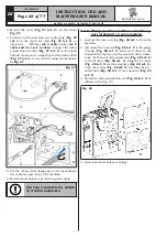
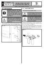
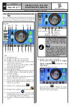
7. Fit the cone (
Fig. 35 ref. 3
) with the narrowest part
turned towards the wheel.
8. Fit the pressure ring (
Fig. 35 ref. 1
) in the nut
(
Fig. 35 ref. 2
) and fasten the cone (
Fig. 35
ref. 3
).
Fig. 35
THE PRESSURE RING (FIG. 35
REF. A) MUST BE FITTED WITH
THE TEETH OR DISCHARGE SIDE
FACING THE LOCKING RING NUT
(SEE FIG. 35).
12.2 Wheel assembly
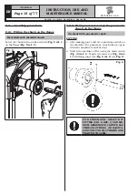
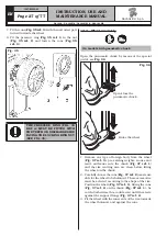
On models with pneumatic chuck
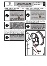
Open the pneumatic chuck by means of the special
pedal, see
Fig. 36
.
Fig. 36
Open/close the
pneumatic chuck
Brake the wheel
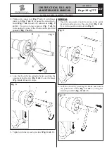
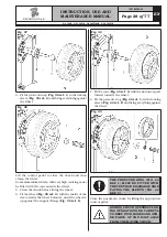
1. Remove any type of foreign body from the wheel
(
Fig. 37 ref. 3
): pre-existing weights, stones and
mud, and make sure the chuck (
Fig. 37 ref. 1
)
and the rim centring area are clean before fitting
the wheel on the chuck.
2. Carefully choose the cone (
Fig. 37 ref. 2
) most suit-
able for the wheel to be balanced. These accessories
must be selected according to the shape of the rim.
Position the wheel (
Fig. 37 ref. 3
), fitting the cone
(
Fig. 37 ref. 2
) on the chuck (
Fig. 37 ref. 1
): be
careful (otherwise this could seize) until this rests
against the support flange (
Fig. 37 ref. 4
).
3. Fit the wheel with the inner side of the rim towards
the wheel balancer and against the cone.
1297-M005-03
RAVAGLIOLI S.p.A.
G4.140R - G4.140WS - G4.140WSLB - GP4.140WS

