INSTRUCTION, USE AND
MAINTENANCE MANUAL
EN
Page 19 of 77
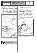
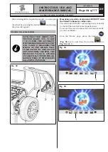
Fig. 16
DURING THIS OPERATION PAY
PARTICULAR ATTENTION TO
(POWER SUPPLY/SIGNAL/USB)
CABLES CONNECTIONS TO THE
MONITOR, IN ORDER NOT TO
DAMAGE THEM AND TO ENSURE
PRODUCT’S CORRECT OPERA-
TION.
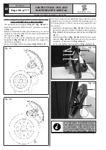
4. Fix the guard (
Fig. 17 ref. 1
) to the monitor sup-
port (
Fig. 17 ref. 2
) with the screws (
Fig. 17
ref. 3
) and the washers (
Fig. 17 ref. 4
) supplied.
Fig. 17
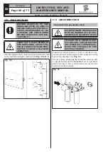
9.2.5 Fitting the protection guard
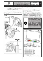
1. Mount the protection guard (
Fig. 18 ref. 1
) to the
support (
Fig. 18 ref. 2
) using the screws (
Fig. 18
ref. 3
), interposing the Belleville washers (
Fig. 18
ref. 4
) and the tab washers (
Fig. 18 ref. 5 - 6
).
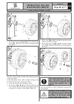
2. Tighten the screws (
Fig. 18 ref. 3
) in order to
make the guard (
Fig. 18 ref. 1
) lift or lower with-
out bumping against the limit switch. Carry out the
adjustment so that it's possible to manually guide
the guard both during closing and opening.
DURING GUARD ASSEMBLY,
PAY ATTENTION TO THE MICRO
PLACED INSIDE THE MACHINE.
Standard on some models
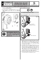
3. Connect the ultrasound sensor cable (
Fig. 18
ref. 7
) of the automatic width measuring device
(
Fig. 19 ref. 9
) to the provided connector (
Fig. 18
ref. 8
).
4. At the end of the connection, introduce the con-
nectors in wheel cover slot (
Fig. 18 ref. 10
), as
illustrated in
Fig. 18. Eventually, fasten connec-
tor’s cable
(
Fig. 18 ref. 8
) with a clamp (
Fig. 18
ref. 11
).
1297-M005-03
RAVAGLIOLI S.p.A.
G4.140R - G4.140WS - G4.140WSLB - GP4.140WS


