INSTRUCTION, USE AND
MAINTENANCE MANUAL
EN
Page 21 of 77
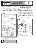
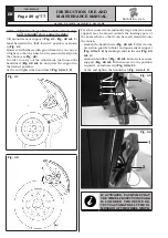
3. Connect connector (
Fig.
21 ref. 1
) of the cable
coming from inside the machine to connector
(
Fig.
21 ref. 2
) of the cable coming from the gauge
arm. Fit the section of the cable with the connectors
inside the arm (
Fig.
21 ref. 3
).
4. Fasten the cable with clamps.
5. Enable the external data gauge and carry out the
device calibration.
Fig. 21
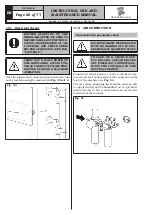
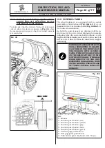
6. Mount machine rear covering (
Fig.
22 ref. 1
) using
the screws (
Fig.
22 ref. 2
) and washers (
Fig.
22
ref. 3
), supplied.
Fig. 22
9.2.7 Fitting of external data gauge / Run-out
(optional on some models)
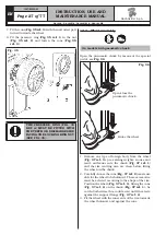
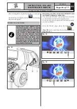
1. Remove the rear covering (
Fig. 23 ref. 1
) from the
machine.
2. Introduce the 4 screws (
Fig. 23 ref. 2
) to the gauge
bracket (
Fig. 23 ref. 3
) and screw them to the
threaded rivets placed on the rear side of the frame.
Insert arm stiffener (
Fig. 23 ref. 4
) into the gauge
arm (
Fig. 23 ref. 5
) and fix them to the bracket
(
Fig. 23 ref. 3
) using 2 screws (
Fig. 23 ref. 6
)
and the washers (
Fig. 23 ref. 7
). Lock the screws
(
Fig. 23 ref. 6
) with the nuts (
Fig. 23 ref. 8
) so
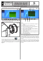
that the shaft and the gauge arm are levelled out
(see
Fig. 24)
.
Fig. 23
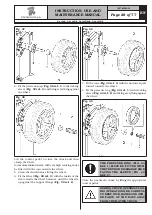
3. Also make sure the gauge tip (
Fig. 24 ref. 1
) is
positioned at the centre of the chuck.
Fig. 24
1297-M005-03
RAVAGLIOLI S.p.A.
G4.140R - G4.140WS - G4.140WSLB - GP4.140WS


