EN
Page 18 of 77
INSTRUCTION, USE AND
MAINTENANCE MANUAL
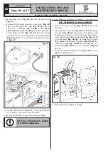
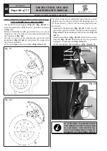
Fig. 13
3. Connect the plugs on the power supply sockets and
monitor signal. Connect the wiring of the keyboard.
4. Fix the guard (
Fig. 14 ref. 1
) to the support
(
Fig. 14 ref. 2
) with the screws (
Fig. 14 ref. 3
)
and the washers (
Fig. 14 ref. 4
) supplied.
Fig. 14
9.2.4 Touch-screen monitor fitting (option-
al)
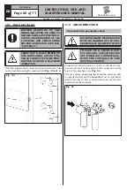
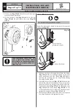
1. Unscrew the nuts (
Fig. 15 ref. 1
) and the washers
(
Fig. 15 ref. 2
) from the screws (
Fig. 15 ref. 3
).
Fit the monitor support (
Fig. 15 ref. 4
) rotated
through 90°. Then screw the previously unscrewed
nuts and washers again.
2. Make the cables (
Fig. 15 ref. 5
) pass into the
plate’s hole (
Fig. 15 ref. 6
) and fix the latter to
the monitor support (
Fig. 15 ref. 4
) by means of
the supplied screws (
Fig. 15 ref. 7
) and washers
(
Fig. 15 ref. 8
).
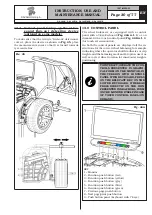
Fig. 15
DURING THIS OPERATION PAY
PARTICULAR ATTENTION TO THE
POWER SUPPLY CABLE, TO THE
HDMI CABLE AND TO THE USB
CABLE
(
FIG. 15 REF. 5
)
IN ORDER
NOT TO DAMAGE THEM.
MAKE SURE THEY HAVE BEEN
INTRODUCED IN THE SUPPORT
PIPE, AS SHOWN IN FIG. 15.
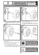
3. Connect the cables to the monitor
Fig. 16 ref. 1
),
as shown in
Fig. 16
(USB cable
ref. 2
, HDMI cable
ref. 3
, power supply cable
ref. 4
).
Fix the monitor (
Fig. 16 ref. 1
) to the plate (
Fig. 16
ref. 5
) with the screws (
Fig. 16 ref. 6
) and the
washers (
Fig. 16 ref. 7
) supplied.
RAVAGLIOLI S.p.A.
1297-M005-03
G4.140R - G4.140WS - G4.140WSLB - GP4.140WS


