4
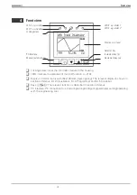
Front view
LED 2
e.g. cooling
LED 3
e.g. alarm 1
LED 1
e.g. heating
LED 4
e.g. alarm 2
Locking screw
Display
e.g. trend
Selector key
PC interface
Increment key (
z
)
Manual/automatic key
Decrement key (
u
)
q
Locking screw: locks the controller module in the housing.
q
LEDs: indicate the statuses of the LED function (
r
q
Display: LCD dot matrix with (64x128 dots, back lighting). The relevant display is shown in
sections 4 Menus, 6.12 Visualization, 6.14 Programmer and 6.15 Controller.
q
Keys
HDIM
: The relevant function is described in section 4 Menus.
q
PC interface: PC connection for structuring/wiring/configuring/parameter setting/operating
with the engineering tool.
9499 040 50611
Front view
13
Содержание KS 98
Страница 8: ...Description 9499 040 50611 Construction 8...
Страница 10: ...Important technical data 9499 040 50611 Further external in and outputs 10...
Страница 12: ...Versions 9499 040 50611 I O modules for units with modular option c basic card 12...
Страница 14: ...Front view 9499 040 50611 14...
Страница 16: ...Mounting 9499 040 50611 16...
Страница 26: ...Maintenance 9499 040 50611 Further information 26...
Страница 36: ...Scaling and calculating functions 9499 040 50611 LG10 10s logarithm 36...
Страница 74: ...Signal converters 9499 040 50611 MEAN mean value formation 74...
Страница 128: ...KS98 I O extensions with CANopen 9499 040 50611 RM_DMS strain gauge module 128...
Страница 132: ...CSEND Send mod blockno s 21 23 25 27 No 57 132...
Страница 140: ...Description of KS98 CAN bus extension 9499 040 50611 140...
Страница 202: ...Controller 9499 040 50611 Process value calculation 202...


